Compound type hydraulic coupler with casing provided with side auxiliary chamber and starter

A technology of hydraulic coupling and side auxiliary chamber, which is applied in transmission devices, fluid transmission devices, belts/chains/gears, etc., can solve the problems of low power, high cost and low efficiency, and achieve transmission power and transmission efficiency. Increased, high average speed, easy maintenance effects

Inactive Publication Date: 2015-10-14
广州市志变制能科技有限责任公司
View PDF0 Cites 1 Cited by
  • Summary
  • Abstract
  • Description
  • Claims
  • Application Information

AI Technical Summary

Problems solved by technology

[0002] At present, hydraulic couplings are designed according to the principles of hydrostatics, etc., the power it can transmit is not large, and the efficiency is not high; in addition, the cost is high

Method used


Image

  • Compound type hydraulic coupler with casing provided with side auxiliary chamber and starter
  • Compound type hydraulic coupler with casing provided with side auxiliary chamber and starter

Examples


Embodiment 1

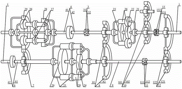
[0025] Such as figure 1 As shown in , a hydraulic coupling and starter with a composite housing with side auxiliary chambers, including an input shaft 1, a fixed one-way clutch 3, a hydraulic coupling 4 with a side auxiliary chamber in the housing, an output shaft 5, an air Gear shift mechanism 6, input gear 7, output gear pair 8, coupling shaft 9, starter gear pair 10, electromagnetic clutch 11, input starter gear pair 12, overrunning clutch 13, between the input shaft 1 and the output shaft 5 Planetary gear 20, input planet carrier 21, input gear 22, output gear 23, fixed gear 24, output planet carrier 25, input large gear 26, fixed planet carrier 27, output ring gear 28, input ring gear 29, input shaft 1 is connected with the output gear 122 of the input starting gear pair 12 and the input end 131 of the overrunning clutch 13, and the output end 132 of the overrunning clutch 13 is connected with the input planet carrier 21 and the output gear 102 of the starter gear pair 10...

Embodiment 2

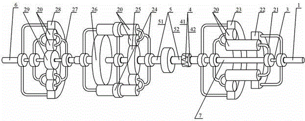
[0032] Such as figure 2 As shown in , a hydraulic coupling with a composite housing with side auxiliary chambers, including an input shaft 1, a coupling shaft 3, a one-way clutch 4, a hydraulic coupling 5 with a housing with side auxiliary chambers, an output shaft 6, an output Coupling shaft 7, planetary gear 20, output planetary carrier 21, input small ring gear 22, input large ring gear 23, connecting planetary carrier 24, output gear 25, fixed gear are arranged between the input shaft 1 and output shaft 6 26. Input planet carrier 27, output ring gear 28, input gear 29, input shaft 1 is connected with input pinion gear 22 and coupling shaft 3, coupling shaft 3 is connected with input gear 29, input pinion gear 22 passes through output planet carrier 21 The planetary gear 20, the output planetary carrier 21 and the input large ring gear 23 cooperate with each other, the output planetary carrier 21 is connected to the output coupling shaft 7, the output coupling shaft 7 is c...


PUM


Abstract

The invention provides a compound type hydraulic coupler with a casing provided with a side auxiliary chamber and a starter. The key point of the technical scheme is that an input shaft (1) is connected with an input starting gear pair (12) and an overrunning clutch (13); the overrunning clutch (13) is connected with an input planet carrier (21) and a starter gear pair (10); an output gear (23) is connected with an output gear pair (8); and a connecting shaft (9) is connected with a neutral gear-engaging mechanism (6), an input large gear (26), the output gear pair (8) and an electromagnetic clutch (11). The neutral gear-engaging mechanism (6) is connected with an output shaft (5); the electromagnetic clutch (11) is connected with the input starting gear pair (12); an output planet carrier (25) is connected with an input gear (7); the input gear (7) is meshed with an input tooth ring (29); an output tooth ring (28) is connected with a hydraulic coupler (4) with the casing provided with the side auxiliary chamber; and the hydraulic coupler (4) with the casing provided with the side auxiliary chamber is connected with an input gear (22) and a fixed one-way clutch (3).

Description

technical field [0001] The invention belongs to the field of hydraulic couplings and starters, more specifically, it is a hydraulic coupling and a starter with a composite casing with side auxiliary chambers for various ground vehicles, ships, railway locomotives and machine tools. Background technique [0002] At present, hydraulic couplings are designed according to the principles of hydrostatics, etc., and the power they can transmit is not large, and the efficiency is not high; in addition, the cost is high. Contents of the invention [0003] The invention overcomes the deficiencies of the prior art, and provides a hydraulic coupling and a starter with a composite casing with side auxiliary chambers, which can prolong the service life of the engine, have simple structure, convenient operation, low cost, energy saving and high efficiency. [0004] In order to realize the purpose of the present invention, the technical scheme that the present invention adopts is as follo...

Claims


Application Information

Patent Timeline
Patent Type & Authority Applications(China)
IPC IPC(8): F16H47/08
CPCF16H47/08
Inventor 吴志强
Owner 广州市志变制能科技有限责任公司
Why Eureka
Try Eureka