


Quick Research
Generate reliable direction feasibility study reports for your R&D in just a few steps.

Technical Q&A
Discover and master advanced knowledge NOW. Basics, ideas, possibilities, all at once.

Find Solutions
As an expert in R&D theories, this can generate solutions to your technical problems instantly.

Evaluate Feasibility
Analyze your overall solution with one click, know your potential R&D risks in advance.

Monitor Landscape
Get weekly tech updates, stay abreast of the latest tech innovations and key insights.
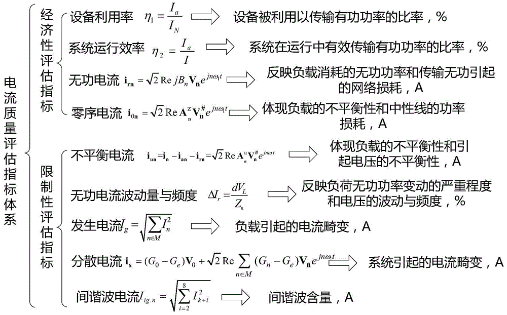
Electric power system current quality assessment method
A current quality evaluation and power system technology, applied in the direction of measuring electrical variables, measuring current/voltage, measuring devices, etc., to achieve clear physical concepts, strong versatility, and clear thinking
- Summary
- Abstract
- Description
- Claims
- Application Information
AI Technical Summary
Problems solved by technology
Method used
Image

Examples
Embodiment 1
[0026] Example 1: Single Phase System
[0027] Step 1: In each spectrum analysis time window T, collect the voltage v current signal i at the PCC point of the system;
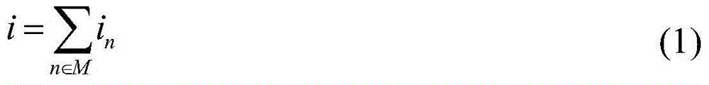
[0028] Step 2: Perform Fourier decomposition of the collected voltage and current signals to obtain the waveform sets of voltage and current. Since the measurement window of 10 cycles is used in the calculation, the harmonic set N and interharmonics can be obtained at the same time Set N i , what is needed here are the harmonic and interharmonic subsets of the current and the harmonic subset of the voltage;
[0029] i = Σ n ∈ M i n - - - ( 1 )
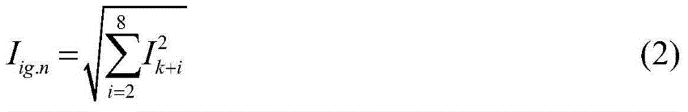
[0030] I i g . n = ...
Embodiment 2
[0062] Example 2: Three-phase three-wire system
[0063] Step 1: In each spectrum analysis time window T, collect the voltage v at the PCC point of the system A , v B , v C and the current signal i A i B i C ;
[0064] Step 2: According to the voltage and current signals in the time window described in step 1, perform Fourier decomposition on the voltage and current signals to obtain the waveform set of voltage and current. Since the measurement window of 10 cycles is used in the calculation , so the harmonic set N and the interharmonic set N can be obtained at the same time i , what is needed here are the harmonic and interharmonic subsets of the current and the harmonic subset of the voltage;
[0065] i ⊥ = Σ n ∈ M i ⊥ n ( ⊥ = A ...
Embodiment 3
[0109] Example 3: Three-phase four-wire system
[0110] Step 1: In each spectrum analysis time window T, collect the voltage v at the PCC point of the system A , v B , v C and the current signal i A i B i C ;
[0111] Step 2: According to the voltage and current signals in the time window described in step 1, perform Fourier decomposition on the voltage and current signals to obtain the waveform set of voltage and current. Since the measurement window of 10 cycles is used in the calculation , so the harmonic set N and the interharmonic set N can be obtained at the same time i , what is needed here are the harmonic and interharmonic subsets of the current and the harmonic subset of the voltage;
[0112] i ⊥ = Σ n ∈ M i ⊥ n ( ⊥ = A ...
PUM
 Abstract
Description
Claims
Application Information
 - R&D Engineer
- R&D Manager
- IP Professional
- Industry Leading Data Capabilities
- Powerful AI technology
- Patent DNA Extraction
Browse by: Latest US Patents, China's latest patents, Technical Efficacy Thesaurus, Application Domain, Technology Topic, Popular Technical Reports.
© 2024 PatSnap. All rights reserved.Legal|Privacy policy|Modern Slavery Act Transparency Statement|Sitemap|About US| Contact US: help@patsnap.com