
An ultra-low emission dust removal device and ash removal method

A dust removal device and ultra-low technology, applied in separation methods, chemical instruments and methods, dispersed particle separation, etc., can solve the problems of low effective filtration area of ​​dust collectors, low filter filtration efficiency, and high equipment operating resistance, and achieve equipment maintenance. The effect of less workload, low operation and maintenance costs, and low operating resistance

Active Publication Date: 2017-02-08
FOSHAN S L P SPECIAL MATERIALS
View PDF4 Cites 0 Cited by
  • Summary
  • Abstract
  • Description
  • Claims
  • Application Information

AI Technical Summary

Problems solved by technology

In this way, under the condition of the same floor area, the effective filtration area of ​​the dust collector is relatively low, and the filtration wind speed is relatively high, which makes the filtration efficiency of the filter relatively low, the dust emission concentration is relatively high, and the equipment operation resistance is relatively high.
[0016] In addition, due to the external compressed air used in the existing pulse ash removal air source, the ash removal energy consumption is relatively high

Method used


Image

  • An ultra-low emission dust removal device and ash removal method
  • An ultra-low emission dust removal device and ash removal method
  • An ultra-low emission dust removal device and ash removal method

Examples


Embodiment Construction

[0052] The preferred embodiments of the present invention will be described below in conjunction with the accompanying drawings. It should be understood that the preferred embodiments described here are only used to illustrate and explain the present invention, and are not intended to limit the present invention.

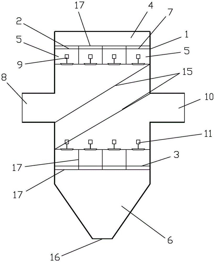
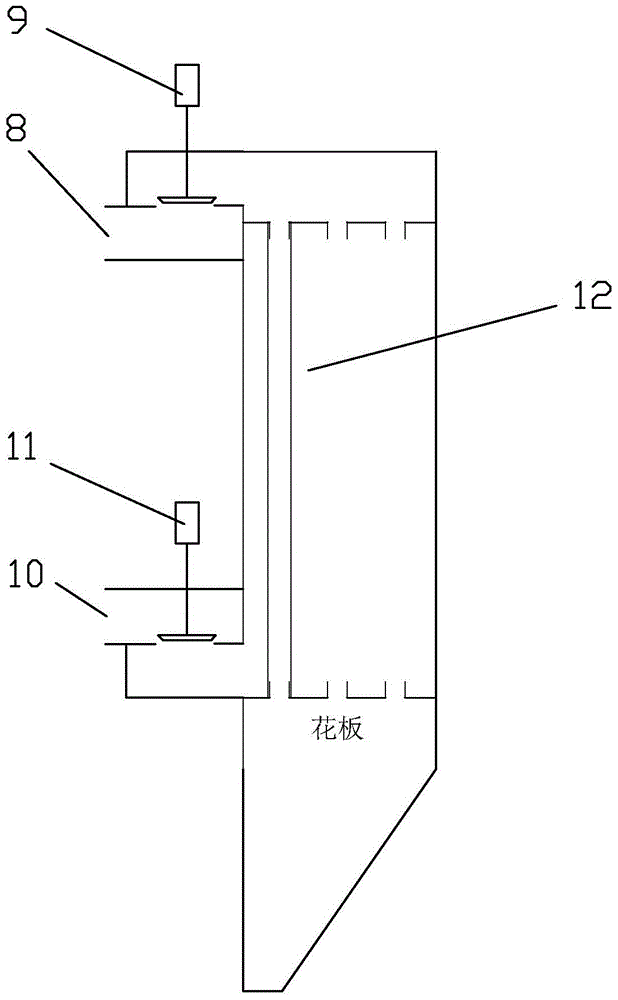
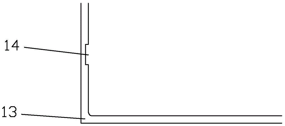
[0053] Such as Figures 1 to 3 As shown, the structure of an ultra-low emission dust removal device according to the present invention is as follows: the dust collector 1 is provided with a shell outside, and the partition plate 17 divides the dust collector 1 into three parts, the upper part is the dust-laden flue gas inlet channel 4, and the middle part is For the filter chamber 5, the partition 17 divides the dust collector 1 into several filter chambers 5 at the same time. The upper flower plate 2 and the lower flower plate 3 are arranged in the filter chamber 5, and the ash hopper 6 is arranged under the lower flower plate 3, and the filter bag The inside of 12...


PUM

PropertyMeasurementUnit
lengthaaaaaaaaaa
depthaaaaaaaaaa
widthaaaaaaaaaa

Abstract

The present invention is an ultra-low emissions dust-removal apparatus and an ash removal method thereof. According to the apparatus, a dust removal device is divided into a plurality of filtration chambers, the upper portions of the filtration chambers are communicated with a gas inlet channel and are provided with gas inlet valves, the middle portions of the filtration chambers are communicated with a gas outlet channel and are provided with gas outlet valves, a vertical filtration bag is arranged between two tubesheets, an ash hopper is arranged below the lower tubesheet, and the internal of the filtration bag is communicated with the ash hopper. The ash removal method of the apparatus comprises: closing the gas inlet valve, maintaining the gas outlet valve at the opening state, closing the gas outlet valve after a few seconds, opening the gas inlet valve after a few seconds, closing the gas inlet valve for a few seconds after opening the gas inlet valve for a few seconds, and then opening the gas outlet valve so as to complete the one ash removal period. The apparatus has advantages of simple equipment, low maintenance workload, low operation and maintenance cost, and long filtration bag service life. According to the ash removal process, the pressures on both sides of the filtration bag produce the fluctuation through the opening and the closing of the gas inlet valve and the gas outlet valve so as to make the filtration bag deform and shake to form the self-cleaning type ash removal way having the ash removal effect, such that the operating energy consumption is substantially reduced.

Description

technical field [0001] The invention belongs to the technical field of dust removal and filtration, and in particular relates to an ultra-low emission dust removal device and a dust removal method. Background technique [0002] At present, the mainstream technologies for reducing the emission concentration of smoke and dust and improving the efficiency of the dust removal system include wet electrostatic precipitator technology, low-temperature electrostatic precipitator technology, and bag filter technology. [0003] The wet electrostatic precipitator is usually arranged after the desulfurization absorption tower, which can effectively remove the soot particles PM2.5, SO 3 Pollutants such as micro-droplets, mercury, and desulfurized gypsum droplets carried in the flue gas after the demister are an efficient electrostatic precipitator. Unlike the dry electrostatic precipitator, which vibrates the ash on the plate to the ash hopper, the wet electrostatic precipitator sprays ...

Claims


Application Information

Patent Timeline
Patent Type & Authority Patents(China)
IPC IPC(8): B01D46/02B01D46/04
Inventor 李杰琚国峰申景山周思远
Owner FOSHAN S L P SPECIAL MATERIALS
Learn More