
Sliding window limiting and locking device

A limit lock and limit slip technology, which is applied to the suspension device of the wing leaf, door/window accessories, wing leaf parts, etc., can solve problems such as difficult detection and prevention, loss, and threat to residents' lives and properties, and achieve The effect of simple structure, low manufacturing cost and strong versatility

Inactive Publication Date: 2015-09-30
王翔
View PDF7 Cites 0 Cited by
  • Summary
  • Abstract
  • Description
  • Claims
  • Application Information

AI Technical Summary

Problems solved by technology

Statistics show that 95% of burglary cases are caused by thieves hanging from the roof or climbing from an adjacent window to an open window that cannot be locked, and enter the house to steal, and the life and property of the residents have been seriously damaged. Threats and losses have brought endless pressure, reputation, liability risks, and costs to community management. In a community of 1,000 households, one household is robbed every two months on average, but it is not easy to detect and prevent

Method used


Image

  • Sliding window limiting and locking device
  • Sliding window limiting and locking device
  • Sliding window limiting and locking device

Examples


Embodiment Construction

[0025] The present invention includes a limiting plate 1 and a latch 2; wherein:

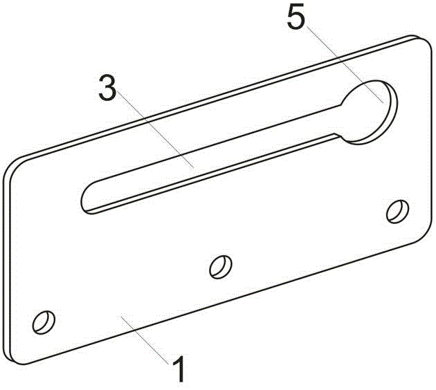
[0026] The limiting plate 1 is a rectangular stainless steel punched sheet, 145mm long and 45mm wide; a hollowed out strip-shaped limiting chute 3 is punched in the length direction of the sheet, 100mm long and 6mm wide; the limiting chute 3 One end close to the adjacent sliding window is provided with an expansion slot area 5, and the expansion slot area 5 is a circle with a diameter of 12mm. Set three equidistant screw holes at the bottom of the limit chute 3 and the lower edge of the limit plate 1; figure 1 shown.

[0027] Use screws to fix the limit plate 1 on the upper edge of the lower frame of the sliding window, and close to the adjacent sliding window, and the limit chute 3 is horizontal; Figure 4 shown.

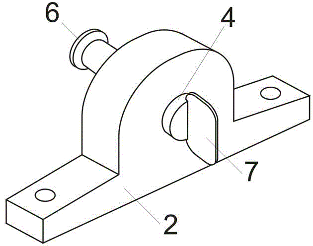
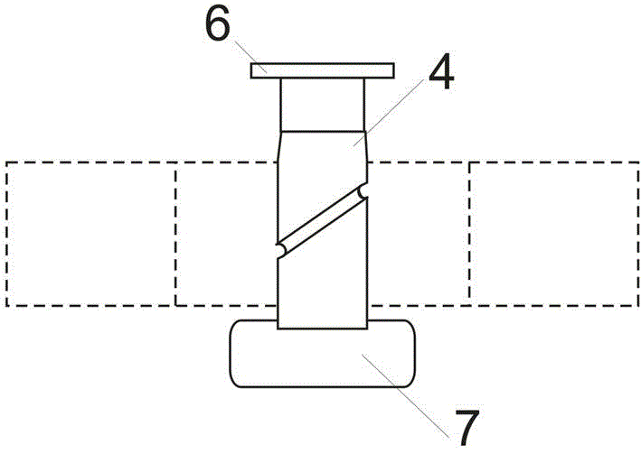
[0028] The latch 2 is made of stainless steel, and is a base with a cylindrical latch hole with a diameter of 8 mm. The latch hole is provided with a cylindrical latch rod 4 with ...


PUM

PropertyMeasurementUnit
Lengthaaaaaaaaaa

Abstract

The invention belongs to the technical field of doors and windows, and particularly discloses a sliding window limiting and locking device. The device comprises a limiting plate and a bolt, wherein the limiting plate is a strip-shaped sheet; a hollow strip-shaped limiting sliding groove is formed in the limiting plate; the lower edge of the limiting plate 1 is arranged at the upper edge of a lower frame of a sliding window; the bolt is a base provided with a bolt hole; a bolt rod capable of moving along the direction of the hole is arranged on the bolt hole; when the sliding window is closed, one end of the bolt rod can be directly inserted into and penetrate through one end, close to the adjacent sliding window, of the limiting sliding groove; an end socket of the bolt rod 4 can slide in the limiting sliding groove; and the base is fixed at the outer edge of a side window frame of the adjacent sliding window. The device has the advantages that the device is simple in structure, low in manufacturing cost and high in universality; an extension displacement distance of the bolt rod utilizes a structural space of the existing sliding window, that is the window frame has a certain thickness, and a certain vertical distance is kept between sliding window glass and the surface of the window frame, so that an extension displacement stroke is provided to the bolt rod; the device is suitable for any sliding window.

Description

technical field [0001] The invention belongs to the technical field of doors and windows, and in particular relates to a sliding window limit locking device. Background technique [0002] In modern buildings, in order to increase the lighting and ventilation standards, the number and area of ​​windows are increased during construction. As a convenient and reliable window structure, sliding windows are widely used in commercial office buildings and residential buildings. The windows are opened and closed by pushing and pulling to circulate the air. [0003] The more windows, the more potential safety hazards. Residents have the habit of opening a window for air circulation, especially in the kitchen, bathroom and living room. And now a crotch is set on the sash of a sliding window in the adjacent two fans, and a latch is set on the sash of the other sliding window, the latch and the crotch can only be made to form a lock when the window is closed. When the two adjacent sli...

Claims


Application Information

Patent Timeline
IPC IPC(8): E05C17/62
Inventor 王翔王平忠
Owner 王翔
Learn More