
Arc-shaped water-blocking drain grating grid-plate for pump station, as well as manufacture, construction and utilization method thereof

A technology of trash racks and grids, which is applied in water conservancy projects, sea area projects, coastline protection, etc., can solve the problems of inconvenient maintenance, inconvenient operation, and unsatisfactory use effects, etc., to achieve convenient operation and save engineering cost , good sealing effect

Inactive Publication Date: 2015-09-30
SUZHOU HUICHENG ZHIZAO IND DESIGN
View PDF7 Cites 0 Cited by
  • Summary
  • Abstract
  • Description
  • Claims
  • Application Information

AI Technical Summary

Problems solved by technology

However, in the long-term operation, the water pump accessories and its power system still often break down, especially the underwater maintenance is more inconvenient. Therefore, it is required to set up maintenance gates in relevant technical specifications such as water conservancy projects to facilitate maintenance; but the operation of the original design is not good. It is convenient, but the use effect is not ideal. This design optimizes the original design and changes it to an arc-shaped rotating water-blocking trash rack. It has the function of a gate when it is closed during use, and it has the function of a trash rack when it is opened. It is used to replace the original Design of trash racks and gates

Method used


Image

  • Arc-shaped water-blocking drain grating grid-plate for pump station, as well as manufacture, construction and utilization method thereof
  • Arc-shaped water-blocking drain grating grid-plate for pump station, as well as manufacture, construction and utilization method thereof
  • Arc-shaped water-blocking drain grating grid-plate for pump station, as well as manufacture, construction and utilization method thereof

Examples


Embodiment 1

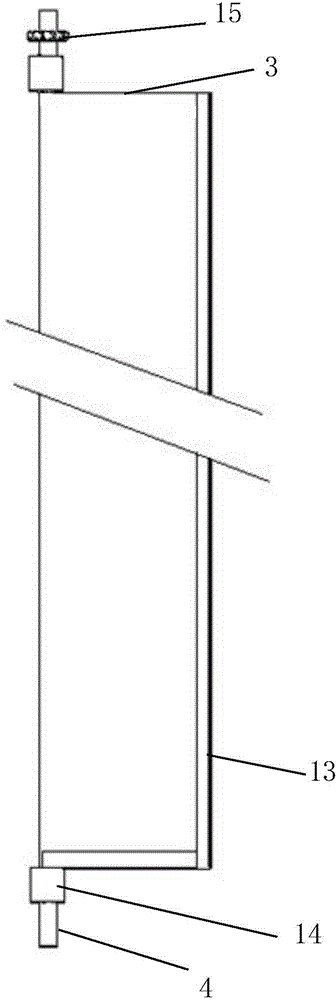
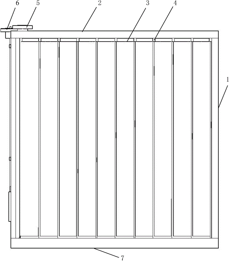
[0036] Embodiment 1: Referring to the accompanying drawings, an arc-shaped water-blocking and trash-retaining grid grid of a pumping station includes a grid 3 and a grid shaft 4. It is characterized in that the grid 3 is arc-shaped and long, and the grid One side of the sheet 3 is provided with a grating shaft 4, and the two ends of the grating shaft 4 protrude from the grating sheet 3 to a certain length and are provided with a bearing 14, and a gear 15 is arranged on the upper part of the bearing 14 of the grating shaft 4 at the upper end. Drive to open and close the trash rack grille.

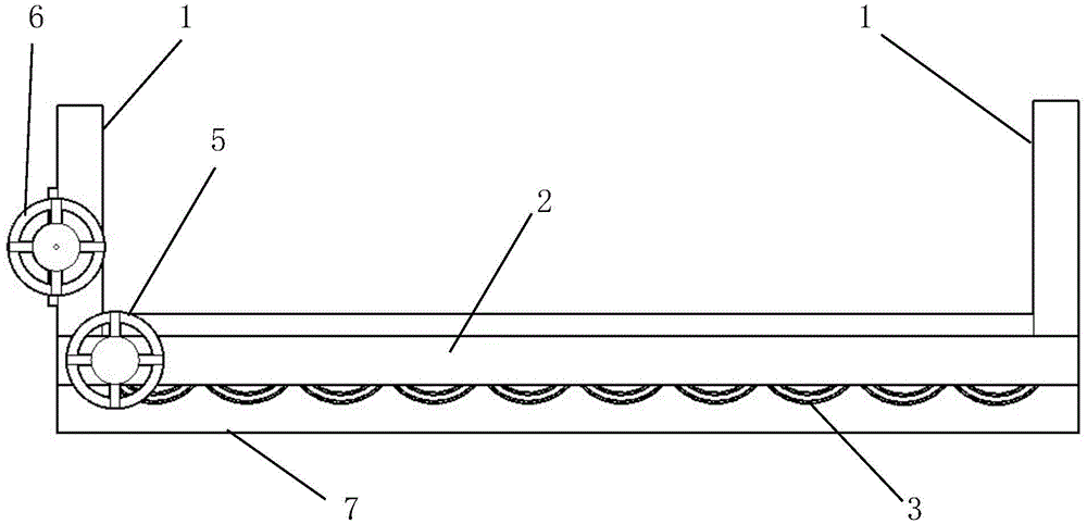
[0037] In a further preferred solution, the width direction of the grid 3 is arc-shaped, and the height of the protruding arc is 3-5 cm. The arc-shaped grid is not easily deformed under water pressure and has a good seal.

[0038] In a further preferred solution, the lower end and the other side of the grating 3 are provided with rubber strips 13, and the soft rubber strips have the effect o...


PUM


Abstract

The invention relates to an arc-shaped water-blocking drain grating grid-plate for a pump station. The arc-shaped water-blocking drain grating grid-plate for the pump station comprises a grid-plate body and a grid-plate shaft, wherein the grid-plate body is arc and long strip-shaped; the grid-plate shaft is arranged on one side of the grid-plate body; the two ends of the grid-plate shaft protrude out of the grid-plate body by a certain length, and a bearing is arranged at each of the two ends; a gear is arranged at the upper part of the bearing at the upper end of the grid-plate shaft; the drain grating grid-plate is opened and closed through the transmission of the gear or a chain. According to the invention multiple groups of the grid-plates are arranged between the top bar and the bottom bar on the pier wall of the pump chamber; all the grid-plates are connected with a grid-plate switching mechanism arranged on the pier wall; when the grid-plate switching mechanism is rotated clockwise, the grid-plates are rotated outwards to be opened and guide water, and the grid-plates form a drain grating to stop sundries from passing; when the grid-plate switching mechanism is rotated anticlockwise, the grid-plates are rotated inwards to be closed to form a gate for stopping water flow from passing. Through the adoption of the arc-shaped water-blocking drain grating grid-plate, land is saved, the project cost is reduced, and sundries can be stopped from entering during water pumping, and the grid-plate can be used as a gate for blocking water during maintenance.

Description

technical field [0001] The application relates to a trash rack device at a water inlet of a pumping station in the field of water conservancy engineering, in particular to an arc-shaped water-blocking trash rack sheet of a pumping station and its manufacturing, construction and use methods. Background technique [0002] In the existing small and medium-sized pumping stations, most of the water inlets are equipped with trash racks, which can prevent weeds from entering the pump impeller and reduce the occurrence of failures. However, in the long-term operation, the water pump accessories and its power system still often break down, especially the underwater maintenance is more inconvenient. Therefore, it is required to set up maintenance gates in relevant technical specifications such as water conservancy projects to facilitate maintenance; but the operation of the original design is not good. It is convenient, but the use effect is not ideal. This design optimizes the origin...

Claims


Application Information

Patent Timeline
Patent Type & Authority Applications(China)
IPC IPC(8): E02B8/02
Inventor 张朝利张朝峰
Owner SUZHOU HUICHENG ZHIZAO IND DESIGN
Learn More