
Concentric circle gas separation device

A technology of gas separation and concentric circles, applied in separation methods, dispersed particle separation, dispersed particle filtration, etc., can solve the problems of low adsorption efficiency of gas separator, uneven air distribution, buckling and deformation of shell structure, etc., and achieve sealing performance Excellent, guaranteed adsorption effect, not easy to buckle and deform

Active Publication Date: 2017-01-25
SCI RES TRAINING CENT FOR CHINESE ASTRONAUTS
View PDF5 Cites 0 Cited by
  • Summary
  • Abstract
  • Description
  • Claims
  • Application Information

AI Technical Summary

Problems solved by technology

[0003] In the gas separator in the prior art, the shell is usually a single-layer cylindrical shape. When the adsorber is working, the airflow enters from the inlet of the adsorber and flows out from the outlet of the adsorber through molecular sieve or activated carbon. When the airflow enters the adsorber, it will impact on the shell, and the existing shell cannot buffer the gas, and the shell structure is prone to buckling deformation; in addition, the airflow is directly blown into the adsorber, and there is a problem of uneven airflow distribution, which makes the adsorption of the gas separator less efficient

Method used


Image

  • Concentric circle gas separation device
  • Concentric circle gas separation device
  • Concentric circle gas separation device

Examples


Embodiment Construction

[0028] The specific implementation manners of the present invention will be further described in detail below in conjunction with the accompanying drawings and embodiments. The following examples are used to illustrate the present invention, but are not intended to limit the scope of the present invention.

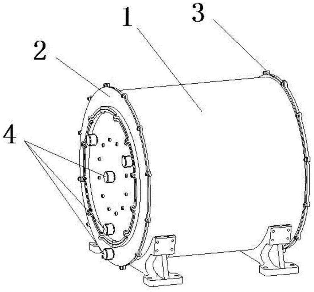
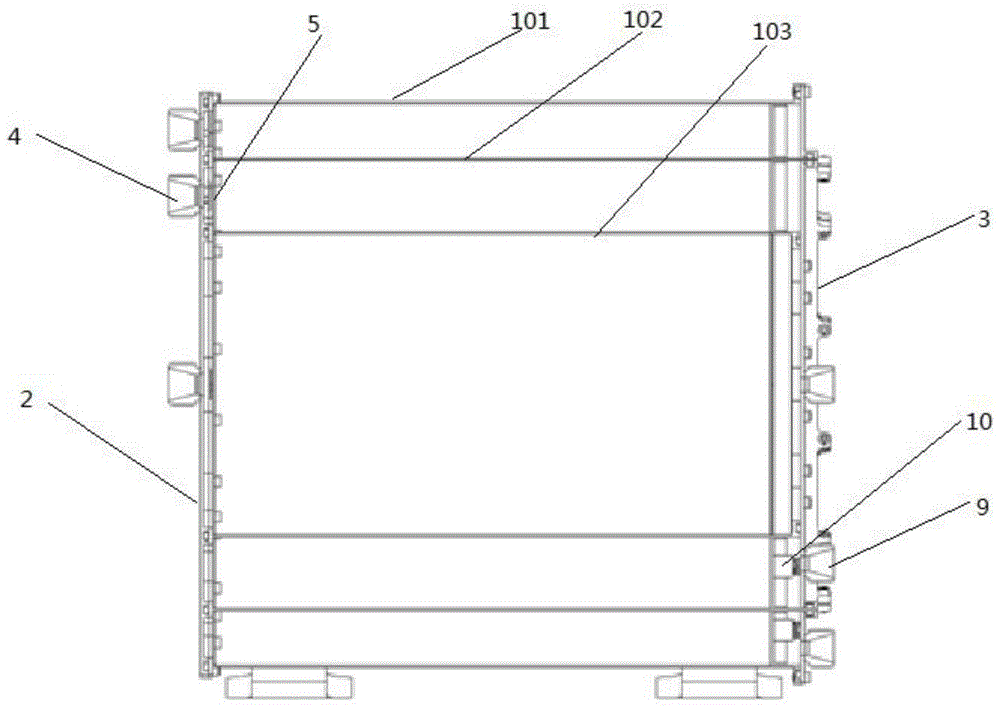
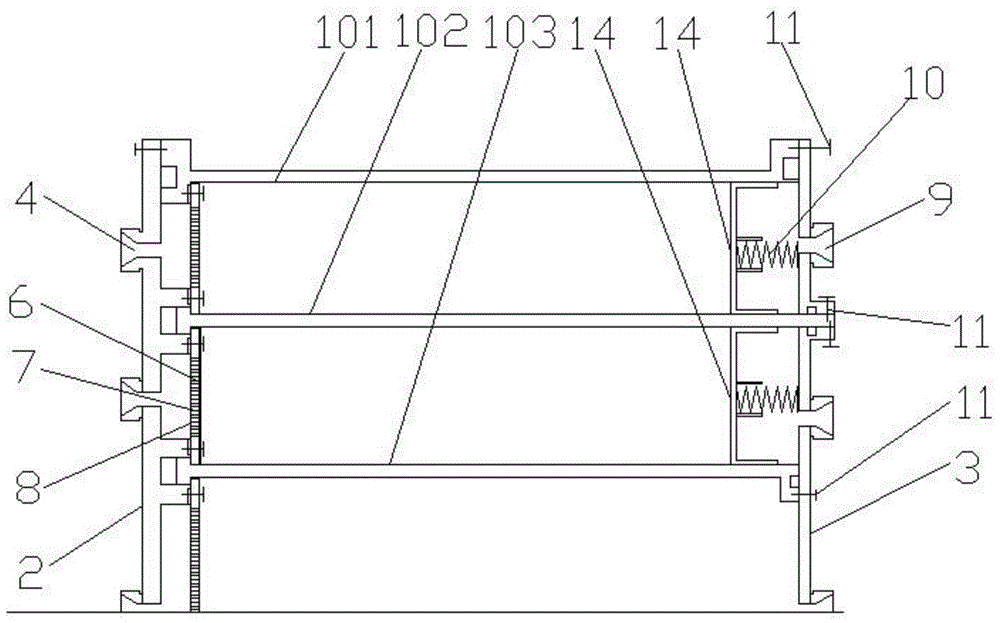
[0029] see Figure 1 to Figure 6 , a concentric gas separation device according to a preferred embodiment of the present invention, comprising a cylinder body 1 and an inlet-side end cover 2 and an outlet-side end cover 3 respectively arranged at both ends of the cylinder body 1, and the inlet-side end cover 2 A number of air inlets 4 are arranged on the top, and a number of air outlets 9 are arranged on the outlet side end cover 3. The air flow enters through the air inlet 4, and flows out from the air outlet 9 after the gas is separated. The cylinder body 1 of the present invention comprises an inner layer cylinder body 103, a middle layer cylinder body 102 and an outer...


PUM


Abstract

The invention relates to a concentric circular gas separation device. The concentric circular gas separation device comprises a barrel body, and an inlet side end cover and an outlet side end cover which are arranged at the two ends of the barrel body respectively, wherein the inlet side end cover is provided with a plurality of gas inlets; the outlet side end cover is provided with a plurality of gas outlets; the barrel body comprises an inner-layer barrel body, a middle-layer barrel body and an outer-layer barrel body which are coaxially arranged; the two ends of the inner-layer barrel body, the middle-layer barrel body and the outer-layer barrel body are in sealed connection with the inlet side end cover and the outlet side end cover respectively; the inlet side end cover is provided with a gas distribution structure for distributing gas flow entering from the gas inlets; and a filtering structure is arranged between one end of the barrel body and the inlet side end cover, and a vibration feeding structure is arranged between the other end of the barrel body and the outlet side end cover. The concentric circular gas separation device can be used for buffering the gas flow and can avoid non-uniform distribution of the gas flow, and the structure is not easy to bend or deform.

Description

technical field [0001] The invention relates to the field of gas separation and purification, in particular to a concentric gas separation device. Background technique [0002] In modern industry, the technology of adsorption and separation of gas by gas separator is widely used in petrochemical, pharmaceutical, metallurgy, electronics and other industries, such as gas separation, drying and air purification, wastewater treatment, oxygen and nitrogen production, etc. Adsorption materials in the gas separator generally use filter materials such as molecular sieves and activated carbon. Molecular sieves or activated carbon can adsorb one or several components in the mixed gas raw material. When the gas passes through the gas separator, one or several components The components are adsorbed, while the other components flow out and are separated to achieve the separation effect. [0003] In the gas separator in the prior art, the shell is usually a single-layer cylindrical shape...

Claims


Application Information

Patent Timeline
Patent Type & Authority Patents(China)
IPC IPC(8): B01D46/00B01D53/04
Inventor 杨润泽胡宏杰韩永强董文平尹永利
Owner SCI RES TRAINING CENT FOR CHINESE ASTRONAUTS
Learn More