a connector

A technology of connectors and bonding sleeves, which is applied in the direction of instruments, light guides, optics, etc., can solve problems such as failure of optical cable connections and failure of bonding sleeves, and achieve the effect of improving the sealing effect and ensuring reliability

Active Publication Date: 2017-08-04
CHINA AVIATION OPTICAL-ELECTRICAL TECH CO LTD
View PDF1 Cites 0 Cited by
  • Summary
  • Abstract
  • Description
  • Claims
  • Application Information

AI Technical Summary

Problems solved by technology

[0004] The purpose of the present invention is to provide a connector to solve the problem that the prior art outdoor optical cable connector cannot ensure that the adhesive sleeve is always relatively fixed with the joint sleeve when the outdoor optical cable connector is in use, which leads to the failure of the optical cable connection

Method used


Image

  • a connector

Examples


Embodiment 1

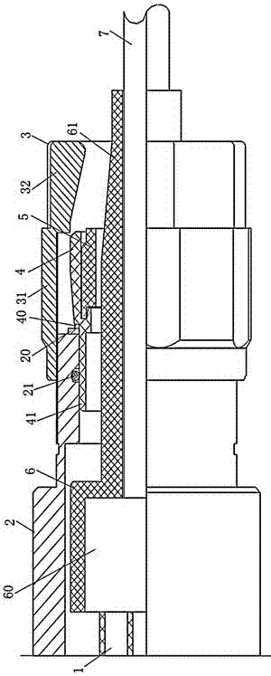
[0018] Embodiment 1 of the connector of the present invention: as figure 1 As shown, it includes a tail attachment and a plug, wherein the tail attachment includes a combination sleeve 2 extending back and forth, and the inside of the combination sleeve has a cavity extending back and forth. , the front end of the bonding sleeve is connected with a plug through the optical fiber 1, and the front end of the bonding sleeve has a glue injection cavity 60, and the glue injection in the glue injection cavity can fix the optical fiber and the outdoor optical cable, and the inner cavity of the bonding sleeve is the front end Large and short stepped type, the stepped surface of the cavity is used to stop and cooperate with the rear end surface of the bonding sleeve to prevent the bonding sleeve and outdoor optical cable from coming out of the rear end of the bonding sleeve, and the rear end of the bonding sleeve is also integrally connected to the direction The extension section 61 ex...


PUM


Abstract

The invention provides a connector comprising a tail accessory which comprises a combining sleeve. The combining sleeve is internally provided with an adhering sleeve which is used for being connected with an outdoor optical cable. The tail part of the combining sleeve is provided with a throat structure and a locking member which is used for enabling the throat structure to radially contract. The rear end of the adhering sleeve is provided with an extension segment which backwardly extends to the throat structure and is used for being matched with the throat structure in a radial direction in an extruding way. The extension segment is internally provided with a channel used for insertion of the outdoor optical cable along a front-and-back direction. The throat structure is enabled to radially contract to be extruded on the extension segment of the adhering sleeve by the locking member in use so that a certain distance is reserved between the rear end of the adhering sleeve and the combining sleeve even a plug and a socket are plugged, the adhering sleeve and the combining sleeve are also maintained to be relatively fixed under the effect of friction force generated by extruding the extension segment via the throat structure, the outdoor optical cable does not backwardly move and the socket and the plug are not separated when the outdoor optical cable is backwardly pulled, and thus connection reliability is guaranteed.

Description

technical field [0001] The invention relates to a connector. Background technique [0002] Optical cable connectors play a very important role in the process of optical signal transmission, especially the optical cable connectors used to connect external optical cables and internal optical cables are widely used in network entry projects. The Chinese invention patent with the authorized announcement number CN100573213C and the authorized announcement date of December 23, 2009 discloses an external optical cable connector, which includes a plug with contacts and a tail attachment. The tail attachment includes a sealing sleeve that is a locking nut, a combination The sealing sleeve and the bonding sleeve, the sealing sleeve is set on the outside of the coupling sleeve, the tail of the sealing sleeve and the coupling sleeve are provided with a shrinking structure, and the outdoor optical cable extends forward from the tail of the coupling sleeve to the opening end of the coupli...

Claims


Application Information

Patent Timeline
Patent Type & Authority Patents(China)
IPC IPC(8): G02B6/38
CPCG02B6/3849G02B6/389
Inventor 王旭涛李卫可徐耕姚文浩韩云钊胡凯刘涛
Owner CHINA AVIATION OPTICAL-ELECTRICAL TECH CO LTD
Why Eureka
Try Eureka