
A tunnel advanced detection device and detection method based on optical fiber current sensor

An optical fiber current and advanced detection technology, which is applied in measurement devices, electrical/magnetic exploration, radio wave measurement systems, etc., can solve the problems of complex and changeable geological conditions, large shields and cutterheads, and difficult insulation.

Inactive Publication Date: 2017-06-20
HUAZHONG UNIV OF SCI & TECH
View PDF2 Cites 0 Cited by
  • Summary
  • Abstract
  • Description
  • Claims
  • Application Information

AI Technical Summary

Problems solved by technology

However, before this method is applied, the cutter head and shield of the TBM need to be insulated. Due to the huge volume, complex structure, and huge force of the shield and cutter head, it is very difficult to insulate, and the geological conditions during the excavation process Complex and changeable, insulation may fail at any time

Method used


Image

  • A tunnel advanced detection device and detection method based on optical fiber current sensor
  • A tunnel advanced detection device and detection method based on optical fiber current sensor
  • A tunnel advanced detection device and detection method based on optical fiber current sensor

Examples


Embodiment Construction

[0024] In order to make the object, technical solution and advantages of the present invention clearer, the present invention will be further described in detail below in conjunction with the accompanying drawings and embodiments. It should be understood that the specific embodiments described here are only used to explain the present invention, not to limit the present invention. In addition, the technical features involved in the various embodiments of the present invention described below can be combined with each other as long as they do not constitute a conflict with each other.

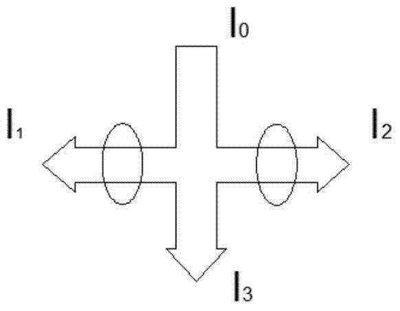
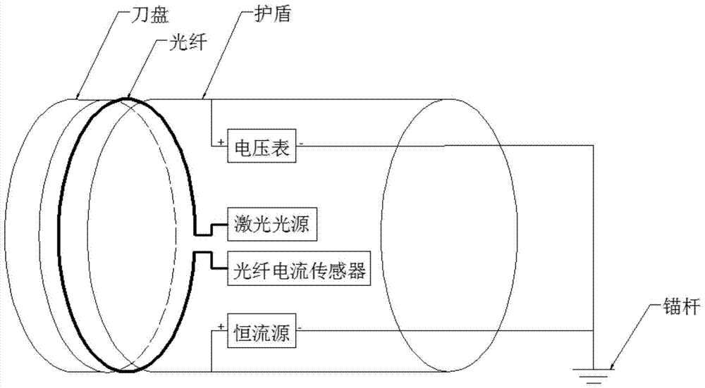
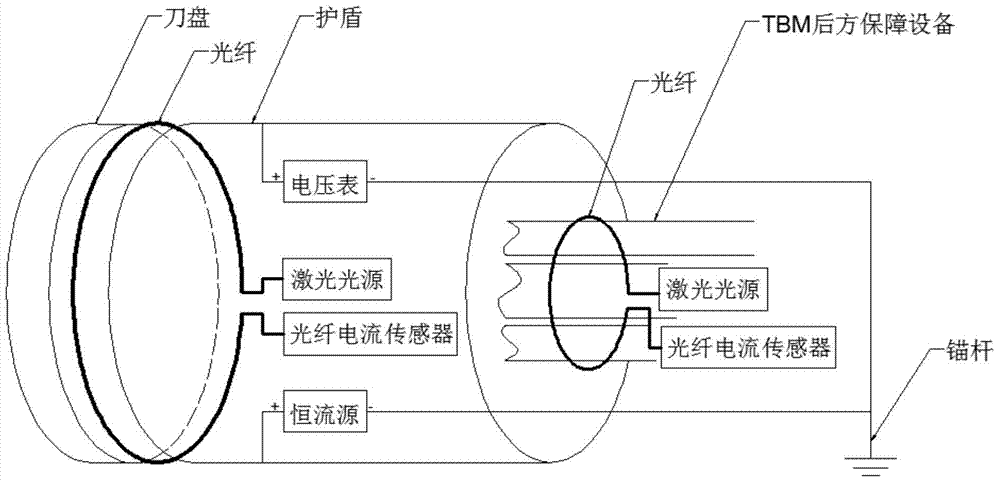
[0025] Firstly, the principle of the device of the present invention is explained. The tunnel advance detection device based on the optical fiber current sensor of the present invention includes a constant current source, a voltmeter, a laser light source, an optical fiber current sensor and an anchor rod. Among them, the constant current source passes the current I to the shield part of the TBM...


PUM


Abstract

The invention discloses a bore-tunneling electrical ahead monitoring device based on an optical fiber current sensor, and a detection method thereof. The bore-tunneling electrical ahead monitoring device is composed of a constant current source, a voltmeter, a laser light source, the optical fiber current sensor and an anchor rod. A tunneling part of a tunnel boring machine (TBM) is supplied with a constant current I, a circle of an optical fiber winds around the rear part of a cutterhead and the rear part of a shield, the magnitude of current on each of the cutterhead, the shield and TBM rear guaranteeing equipment can be obtained by using the optical fiber current sensor, and voltage on the shield is measured for calculating apparent resistance of a geologic body, so as to judge water content and rock class of the geologic body. Compared with the traditional bore-tunneling electrical ahead monitoring method, the bore-tunneling electrical ahead monitoring device based on the optical fiber current sensor omits a great deal of pre-insulating operation.

Description

technical field [0001] The invention belongs to the technical field of tunnel engineering geological prospecting applications, and more specifically relates to a tunnel prospecting device based on an optical fiber current sensor and a detecting method thereof. Background technique [0002] In 2002, the German GEO company developed a tunnel ahead detection system (Bore-Tunneling Electrical Ahead Monitoring, BEAM) based on the focused current method. In order to improve the detection accuracy and directionality, a shielding current of the same phase is passed on the shield of the full-face tunnel boring machine (TBM) to make use of the characteristics of same-sex repulsion" Squeeze" the probe current to concentrate it more toward the front of the palm. However, before this method is applied, the cutter head and shield of the TBM need to be insulated. Due to the huge volume, complex structure, and huge force of the shield and cutter head, it is very difficult to insulate, and ...

Claims


Application Information

Patent Timeline
Patent Type & Authority Patents(China)
IPC IPC(8): G01V3/00
CPCY02A90/30
Inventor 赵斌高昕星
Owner HUAZHONG UNIV OF SCI & TECH
Learn More