
Sleeve Buckling Restrained Brace

A buckling-constrained, sleeve-type technology, applied to building components, shockproof, etc., can solve the problems of long calculation length, large amount of material consumption, and low material utilization rate, so as to save materials, meet architectural requirements, and achieve the best economic efficiency. Effect

Active Publication Date: 2018-12-11
上海研深信息科技有限公司
View PDF6 Cites 0 Cited by
  • Summary
  • Abstract
  • Description
  • Claims
  • Application Information

AI Technical Summary

Problems solved by technology

[0004] At present, there are many structures of buckling-resistant energy-dissipating braces. Experts and scholars in related fields have greatly improved the structure of buckling-resistant energy-dissipating braces, and the economy and process difficulty of buckling-resistant energy-dissipating braces have been greatly reduced.
However, the existing anti-buckling energy-dissipating braces still have the following problems: In recent years, with the rapid development of the national economy, large-span structures or structures with high storey heights or structures with cross-story columns have emerged in large numbers. In the case of energy-dissipating braces, the calculated length of buckling-resistant energy-dissipating braces is relatively long. In order to meet structural requirements, the section of buckling-resistant energy-dissipating braces often does not meet architectural requirements, and the amount of materials used is large, and the utilization rate of materials is not high.

Method used


Image

  • Sleeve Buckling Restrained Brace
  • Sleeve Buckling Restrained Brace
  • Sleeve Buckling Restrained Brace

Examples


Embodiment 1

[0050] Embodiment 1 (all stress-bearing members are all in the form of full length):

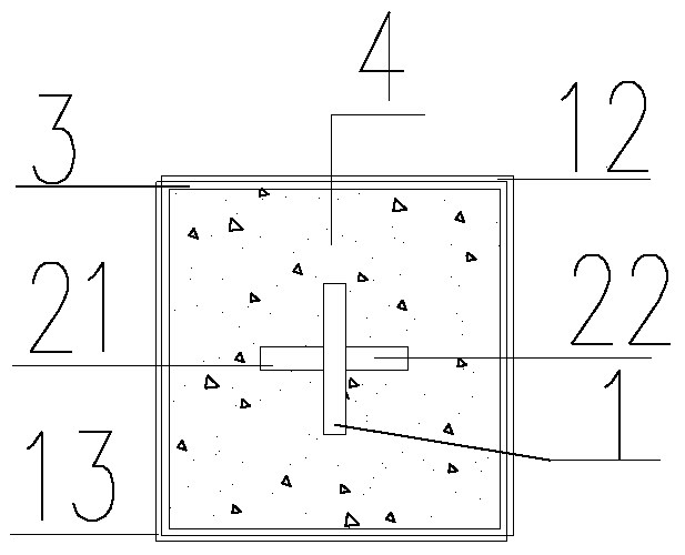
[0051] see figure 1 As shown, it includes the main core force-bearing member 1 and the constraint member. The two ends of the main core force-bearing member 1 are respectively provided with a reinforced structural section, which is called the front non-yielding transformation section, the rear non-yielding transformation section, and the front non-yielding transformation section Including the first sub-core stress member 21, the rear non-yielding transformation section includes a second sub-core stress member 22, the restraint member includes a yield section restraint device for constraining the main core stress member 1, and a non-yielding transition section for constraining the front Left constraint for the segment, right constraint for the post-constraint non-yielding transition segment. The yield section constraint device includes a sleeve 3, a grouting material 4, and an end plate. The...

Embodiment 2

[0062] Embodiment 2 (all stress components are divided into three sections):

[0063] see Figure 8 As shown, in this embodiment, the main core force-bearing member, the first auxiliary core force-bearing member and the second auxiliary core force-bearing member are divided into three sections respectively, wherein the main core force-bearing member is composed of the main connecting plate 1 and the left main connecting plate 16 It is composed of the right main connecting plate 18; the first secondary core force-bearing member is composed of the first secondary connecting plate 21, the left secondary connecting plate 171 and the right secondary connecting plate 191, and the second secondary core force-bearing member is connected by the second secondary Plate 22, left two secondary connecting plates 172 and right two secondary connecting plates 192 form. The outer surface of the main connecting plate 1 is provided with non-adhesive material 21 .

[0064] The main connecting p...


PUM


Abstract

The invention discloses a sleeve-type flexing constraint support, and the support comprises a main core stress component and a constraint component. The central parts of the front and rear sides of the main core stress component are respectively provided with a reinforcing structure segment, and the reinforcing structure segments are called as a front no-yield conversion segment and a rear no-yield conversion segment. The front no-yield conversion segment comprises a first auxiliary core stress component, and the rear no-yield conversion segment comprises a second auxiliary core stress component. The first and second auxiliary core stress components are symmetrically welded at the central parts of the front and rear sides of the main core stress component. The main core stress component, the first auxiliary core stress component and the second auxiliary core stress component form a crossing structure. The constraint component comprises a yield segment constraint device for constraining the main core stress component, a left constraining device for constraining the front no-yield conversion segment, and a right constraining device for constraining the rear no-yield conversion segment. The support can save materials, achieves the optimal economic performance, and can meet the requirements of buildings better.

Description

technical field [0001] The invention relates to the technical field of vibration reduction of construction engineering structures, in particular to a sleeve-type buckling restraint support. Background technique [0002] In recent decades, anti-buckling energy-dissipating braces have been widely used in countries and regions such as the United States, Japan, and Taiwan. The anti-buckling energy-dissipating brace is a kind of brace that does not buckle under tension and compression, and has more stable mechanical properties than traditional braces. The buckling restraint brace can not only improve the stiffness and ductility of the structure, but also use the hysteretic properties of the steel to consume the energy of the structure due to the horizontal load, which is of great significance to the improvement of the seismic capacity of the structure. [0003] The general anti-buckling energy-dissipating brace consists of five parts: constrained yielding segment; constrained no...

Claims


Application Information

Patent Timeline
Patent Type & Authority Patents(China)
IPC IPC(8): E04B1/98
Inventor 田敏
Owner 上海研深信息科技有限公司
Learn More