
Blow molding machine turning clip

A technology of blow molding machine and clamping arm, which is applied in the field of closing clips, which can solve the problems of easily polluted raw materials, insufficient stretching width, and small clamping force, and achieve the effects of avoiding pollution, increasing stretching width, and improving clamping force

Inactive Publication Date: 2015-09-23
QINGDAO YANKANG PLASTIC MACHINERY
View PDF0 Cites 0 Cited by
  • Summary
  • Abstract
  • Description
  • Claims
  • Application Information

AI Technical Summary

Problems solved by technology

[0002] When the blow molding industry uses a blow molding machine for blow molding, it is necessary to use clips to close the plastic raw materials before blow molding; because blow molding should be performed when the plastic raw materials are at a certain temperature and have the best stretchability, Ensure the quality and uniformity of blow molding; this requires that the closing speed should be fast, rapid, and short and thorough; therefore, clamps with large closing force and rapid response are required; general enterprises use hydraulically driven straight arm reverse clamps , the clamping force of this kind of flip clamp is small, the cost is expensive, and it is easy to pollute the raw materials; and when the plastic raw materials are closed tightly, the stretching width is limited by the clamping arm and the outer baffle, and the stretching width is not enough, so it is not suitable for manufacturing. In the application of plastic barrels with large diameters, usually when it is necessary to clamp relatively large barrels for blow molding, it is necessary to replace the flip clamp with a larger stretching range

Method used


Image

  • Blow molding machine turning clip
  • Blow molding machine turning clip
  • Blow molding machine turning clip

Examples


Embodiment Construction

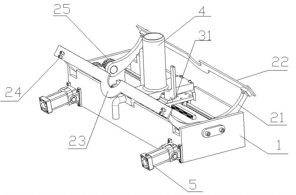
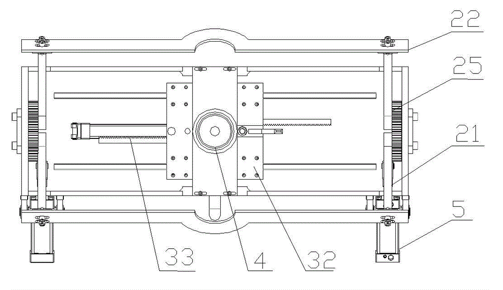
[0013] Such as figure 1 As shown, it includes chassis 1, clamp arm 21, clamp knife 22, bending part 23, bolt 24, gear 25, extension shaft 31, blow seat 4 and cylinder 5;

[0014] The present invention mainly comprises a base frame 1, two pairs of symmetrical clamping arms 21 are respectively arranged on the side walls at both ends of the base frame 1, and the clamping arms 21 are symmetrical arcs, which are arranged in an outwardly protruding arc shape, which can increase the The strength and power loss during the transmission process of the large clamp arms makes the closing more rapid; the bottom end of each clamp arm is respectively fixed on the side wall of the chassis 1 with two gears 25, and the two gears 25 are connected to each other. Impact, synchronous movement; one of each pair of symmetrical arc-shaped clamp arms 21 is connected to the cylinder 5, and the cylinder 5 pushes one of the clamp arms to rotate around the fulcrum, thereby driving the gear of the clamp arm...


PUM


Abstract

The present invention belongs to the blow molding machinery, and in particular relates to a folding clip used for the blow molding machinery, the folding clip includes an underframe, a power mechanism arranged on the underframe, a folding mechanism connected with the power mechanism, and a stretching mechanism, the folding mechanism comprises two pairs of arc-shaped symmetrical clamping arms and face-to-face folding clamping knives arranged on the clamping arms; every two of the arc-shaped symmetrical clamping arms are in gear connection and synchronously move; after the folding mechanism is folded face to face, a gap is left between every two of the arc-shaped symmetrical clamping arms; hydraulic contamination of raw materials can be avoided, the manufacturing cost is greatly reduced, the clamping force of the turning clip is increased, so that the folding can be quick and neat, the folding time is saved, the raw material cooling can be prevented, the product quality can be greatly improved, the product is easier to shape, the stretching width of a stretching shaft is increased, under the premise of no increasing of the manufacturing cost, the folding clip can be better used in the production of larger diameter plastic buckets or blow molding machines, enterprise cost can be saved, and benefits are brought.

Description

technical field [0001] The invention belongs to a blow molding machine, in particular to a clip for closing up on a blow molding machine. Background technique [0002] When the blow molding industry uses a blow molding machine for blow molding, it is necessary to use clips to close the plastic raw materials before blow molding; because blow molding should be performed when the plastic raw materials are at a certain temperature and have the best stretchability, Ensure the quality and uniformity of blow molding; this requires that the closing speed should be fast, rapid, and short and thorough; therefore, clamps with large closing force and rapid response are required; general enterprises use hydraulically driven straight arm reverse clamps , the clamping strength of this kind of flip clamp is small, the cost is expensive, and it is easy to pollute the raw materials; and when the plastic raw materials are closed tightly, the stretching width is limited by the clamping arm and ...

Claims


Application Information

Patent Timeline
Patent Type & Authority Applications(China)
IPC IPC(8): B29C49/42B29C49/28
Inventor 付洪明
Owner QINGDAO YANKANG PLASTIC MACHINERY
Learn More