
Magnetic induction character wheel counter

A magnetic induction and counter technology, applied in the field of data identification, can solve problems such as excessive manual intervention, excessive manual intervention, inaccurate measurement, etc., to increase stability and service life, magnetic field change induction, magnetic field change induction stable effect

Active Publication Date: 2015-09-16
CHENGDU QIANJIA TECH CO LTD
View PDF5 Cites 1 Cited by
  • Summary
  • Abstract
  • Description
  • Claims
  • Application Information

AI Technical Summary

Problems solved by technology

[0003] The purpose of the present invention is to overcome the problem of excessive manual intervention in the installation process caused by the use of reed switches for word wheel counting, and the problem of inaccurate measurement due to micro-leakage, and to provide a magnetic induction chip for counting, thereby avoiding the The production process of the character wheel counting device requires too much manual intervention and the magnetic induction character wheel counter that does not cause inaccurate measurement due to micro-leakage of the reed switch: In order to achieve the above purpose, the technical solution adopted by the present invention is:

Method used


Image

  • Magnetic induction character wheel counter
  • Magnetic induction character wheel counter
  • Magnetic induction character wheel counter

Examples


Embodiment 1

[0024] Example 1: The purpose of the present invention is to overcome the problem of excessive manual intervention in the installation process caused by the use of reed switches for word wheel counting, and the problem of inaccurate measurement due to micro-leakage, and to provide a magnetic induction chip for counting, thereby avoiding the The production process of the character wheel counting device requires too much manual intervention and the magnetic induction character wheel counter that does not cause inaccurate measurement due to micro-leakage of the reed switch: In order to achieve the above purpose, the technical solution adopted by the present invention is:

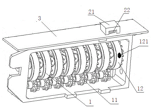
[0025] A magnetic induction character wheel counter, such as figure 1 shown, including,

[0026] Character wheel group 1, the character wheel group includes eight coaxially arranged character wheels, a circle of stepping protrusions is evenly distributed on the circumferential edge of one side of the characte...

Embodiment 2

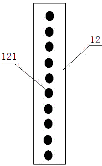
[0032] Example 2: Different from Example 1, as figure 2 As shown, in this embodiment, an iron block 121 is provided at the position of each number on the character wheel 12 provided with ferromagnetic material.

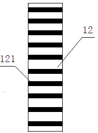
[0033] When in use, as the character wheel 12 provided with iron blocks 121 rotates, whenever an iron block 121 approaches the magnetic block 21 (that is, when a number turns below the magnetic block 21), the magnetic block The magnetic field of 21 changes, and the magnetic induction chip 22 outputs counting pulses after sensing the change of the magnetic field.

[0034] It should be noted that the shape of the iron block 121 is not limited to figure 1 or figure 2 The circle in , but can be any shape, such as image 3 The bars shown. In addition, the iron block can be embedded in the surface of the character wheel 12 or protrude from the surface of the character wheel 12 .

Embodiment 3

[0035] Example 3: The difference between this embodiment and Embodiment 1 is that all the character wheels in the character wheel group 1 are character wheels 12 provided with iron blocks 121, and each character wheel 12 provided with iron blocks 121 corresponds to a magnetic induction unit . In this embodiment, magnetic barrier sheets are provided between the character wheels 12 provided with iron blocks 121 to prevent magnetic interference between the character wheels.


PUM


Abstract

The invention relates to the field of data identification in measurement technologies, and particularly relates to a magnetic induction character wheel counter. The magnetic induction character wheel counter comprises a character wheel group, a magnetic induction unit, wherein the character wheel group comprises more than two coaxially arranged character wheels, and the adjacent character wheels are connected through a carry gear; the character wheel group comprises at least one character wheel provided with a ferromagnetic substance; the ferromagnetic substance is arranged at a position, where at least one number is located, on the character wheel; the magnetic induction unit is in one-to-one correspondence with the character wheel provided with the ferromagnetic substance and is arranged on a circuit board, and the magnetic induction unit comprises a U-shaped magnetic block and a magnetic induction chip arranged in a notch of the magnetic block. The ferromagnetic substance rotating along with the character wheel causes a magnetic field of the magnetic block to change when approaching the corresponding magnetic block. The magnetic induction chip is used for inducing changes in the magnetic field and outputs counting pulses to the circuit board. by adopting the technical scheme provided by the invention, an automatic process with a higher degree can be realized, induction of the magnetic induction chip for changes in the magnetic field of the U-shaped magnetic block is more stable and more accurate at the same time, the stability of the counting device is increased, and the service life of the counting device is prolonged.

Description

Technical field [0001] The invention involves the field of data identification in measurement technology, especially a magnetic induction wheel counter. Background technique [0002] The word wheel counting device in existing technologies is mostly used to install magnetic materials on the word wheel, and the electronic pulse counting is performed through the cadre scruption.Such products have 2 disadvantages: 1. The pipe foot plastic surgery during welding of the cottage is easy to cause a slight leakage of the dry spring tube vacuum glass tube, and this micro leakage is not easy to find, which causes the use of micro -leaking dry scret tunnels.The measurement of the word wheel count is inaccurate after a period of time.2. Incorporation cannot perform the automation process directly during the plastic welding process, and artificial intervention is required, and the production efficiency is not high. Invention content [0003] The purpose of the invention of the present inventi...

Claims


Application Information

Patent Timeline
IPC IPC(8): G06M1/274
Inventor 邵帅刘义胡芸华赵勇
Owner CHENGDU QIANJIA TECH CO LTD
Learn More