protective case
A protective cover and shell technology, applied in the fields of instruments, electrical digital data processing, digital data processing components, etc., can solve the problems of damage, too small touch screen, loss of command input function of the protective cover, etc., to reduce bending Curvature, the effect of improving the service life
- Summary
- Abstract
- Description
- Claims
- Application Information
AI Technical Summary
Problems solved by technology
Method used
Image
Examples
no. 1 example
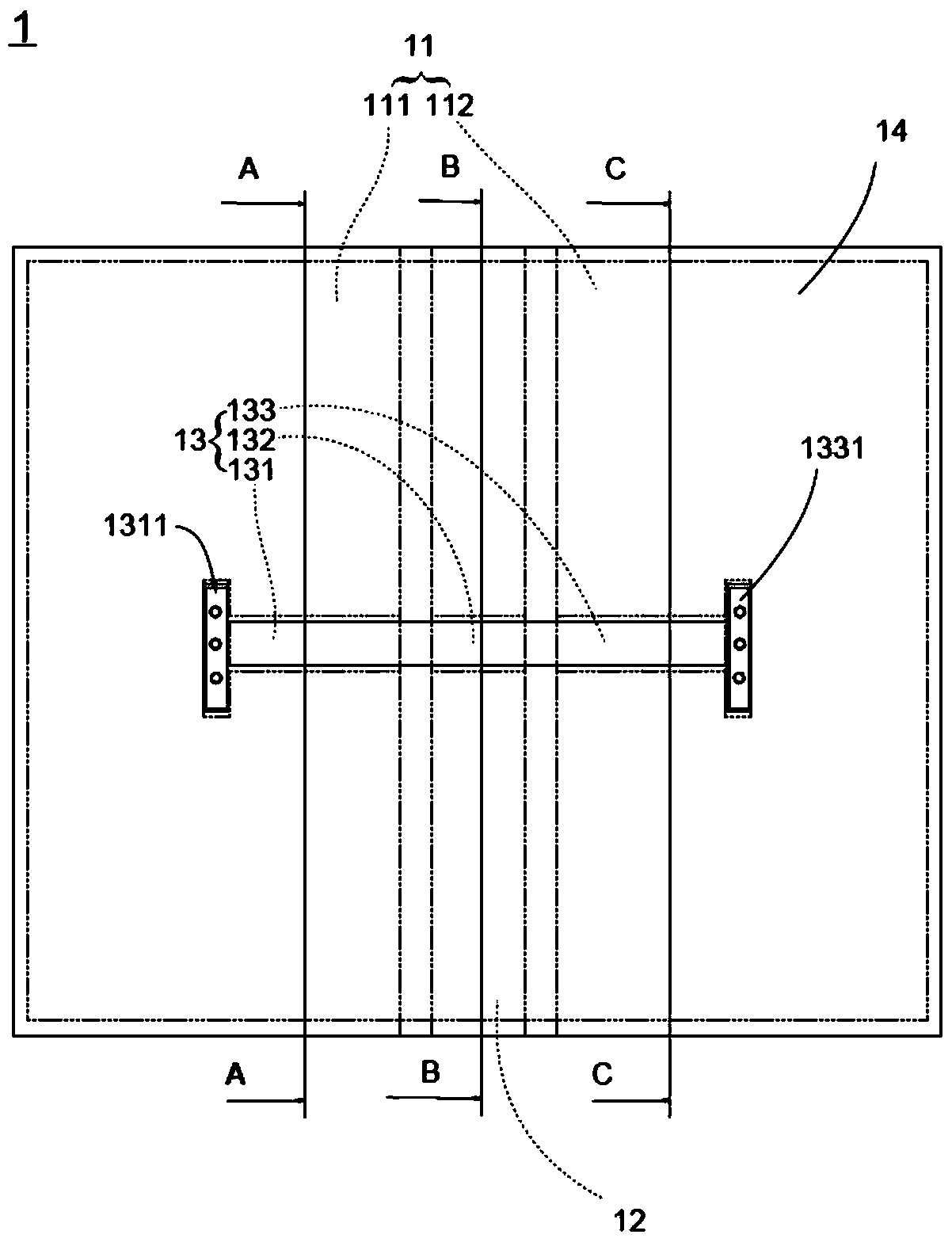
[0055] Such as diagram 2-1 As shown, the first casing 111 of the first embodiment of the present invention has a first casing plate 1112 and a first casing cover 1113 , and the skin 14 is attached to the first casing cover 1113 of the first casing 111 . Wherein, after the first shell plate 1112 is combined with the first shell cover 1113 , the above-mentioned first groove 1111 is formed between the first shell plate 1112 and the first shell cover 1113 .
[0056] Such as Figure 3-1 As shown, the pivoting housing 12 of the first embodiment of the present invention has a pivoting shell plate 121 and a pivoting shell cover 122. The shell plate 121 or the pivoting shell cover 122 is pre-recessed with grooves. Wherein, when the pivoting shell plate 121 is combined with the pivoting shell cover 122 , the above-mentioned pivoting shell groove 123 is formed between the pivoting shell plate 121 and the pivoting shell cover 122 .
[0057] Such as Pic 4-1 As shown, the second casin...
no. 2 example
[0059] Such as Figure 2-2 As shown, the first housing 111 of the second embodiment of the present invention has a first left shell plate 11121, a first right shell plate 11122, an upper first shell cover 11131 and a lower first shell cover 11132, and the skin 14 is attached to On the upper first case cover 11131 and the lower first case cover 11132 of the first housing 111 . Wherein, when the first left shell plate 11121, the first right shell plate 11122, the upper first shell cover 11131 and the lower first shell cover 11132 are combined, the first left shell plate 11121, the first right shell plate 11122, the upper first shell plate 11122 The above-mentioned first groove 1111 is formed between the first shell cover 11131 and the lower first shell cover 11132 .
[0060] Such as Figure 3-2 As shown, the pivoting housing 12 of the second embodiment of the present invention has a left pivoting shell 1211, a right pivoting shell 1212, an upper pivoting shell 1221 and a lower...
no. 3 example
[0063] Such as Figure 2-3 As shown, the protective case 1 of the third embodiment of the present invention has a first adhesive layer 1114 , and the first housing 111 has a first shell plate 1112 and a first shell cover 1113 . The first adhesive layer 1114 is glued and separates the first shell plate 1112 and the first shell cover 1113 , and the above-mentioned first groove 1111 is formed between the first shell plate 1112 and the first shell cover 1113 . Regarding the thickness dimension, the thickness of the first adhesive layer 1114 is greater than the thickness of the first section 131 of the flexible circuit board 13 , so that the first section 131 can extend through the first groove 1111 and change its extension shape.
[0064] Such as Figure 3-3 As shown, the protective cover 1 of the third embodiment of the present invention has a pivoting adhesive layer 124 , and the pivoting housing 12 has a pivoting shell plate 121 and a pivoting shell cover 122 . The pivoting a...
PUM
 Abstract
Description
Claims
Application Information
 - Generate Ideas
- Intellectual Property
- Life Sciences
- Materials
- Tech Scout
- Unparalleled Data Quality
- Higher Quality Content
- 60% Fewer Hallucinations
Browse by: Latest US Patents, China's latest patents, Technical Efficacy Thesaurus, Application Domain, Technology Topic, Popular Technical Reports.
© 2025 PatSnap. All rights reserved.Legal|Privacy policy|Modern Slavery Act Transparency Statement|Sitemap|About US| Contact US: help@patsnap.com


