
Transformer station inspection tour robot positioning navigation system and method

A patrol robot, positioning and navigation technology, applied in navigation calculation tools, two-dimensional position/channel control, instruments, etc., can solve the problem of low positioning accuracy

Active Publication Date: 2015-09-16
STATE GRID INTELLIGENCE TECH CO LTD
View PDF8 Cites 138 Cited by
  • Summary
  • Abstract
  • Description
  • Claims
  • Application Information

AI Technical Summary

Problems solved by technology

[0014] In order to solve the deficiencies in the prior art, the present invention discloses a positioning and navigation system and method for an inspection robot based on a multi-resolution map. Considering that the substation inspection robot needs to accurately stop at a stop before performing an inspection task. Effectively perform patrol inspection tasks, but do not require high positioning accuracy during the operation of the robot between stops. For this reason, the present invention constructs a multi-resolution map that combines laser landmarks, grids, and topologies representing the operating environment of the robot. Using the combination of coarse positioning based on the grid map and fine positioning based on the original data of laser landmarks, the precise positioning of the inspection robot in the substation can be realized under the premise of ensuring the real-time positioning and navigation; at the same time, according to the characteristics of the inspection route of the substation robot, A global path planning method based on topological point classification is proposed, which can effectively improve the calculation efficiency of path planning and reduce storage consumption, and meet the needs of online robot running path planning in some cases.

Method used


Image

  • Transformer station inspection tour robot positioning navigation system and method
  • Transformer station inspection tour robot positioning navigation system and method
  • Transformer station inspection tour robot positioning navigation system and method

Examples


Embodiment Construction

[0083] The present invention is described in detail below in conjunction with accompanying drawing:

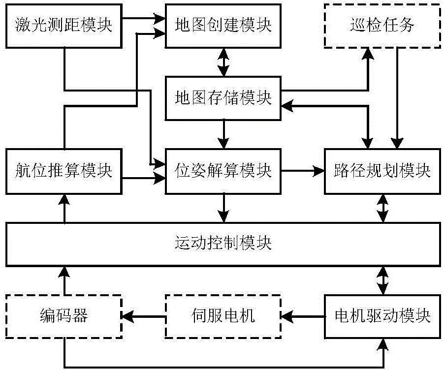
[0084] like figure 1 Shown: A substation inspection robot positioning and navigation system, including: laser ranging module, dead reckoning module, map creation module, map storage module, positioning calculation module, path planning module, motion control module, motor drive module.

[0085] The functions and data connections of each module are as follows:

[0086] Laser ranging module: It consists of a laser ranging sensor fixedly installed on the robot body, and is used to measure the distance information of obstacles around the robot relative to the scanning center of the laser sensor. The acquired data is connected to the map creation module, pose calculation module and path planning module.

[0087] Dead reckoning module: convert the pulse data of the robot drive motor shaft encoder sent by the motion control module into the moving distance and attitude change of the...


PUM


Abstract

The invention discloses a transformer station inspection tour robot positioning navigation system and a method. Confidence obtained by a laser range finding module and a dead reckoning module is outputted to a map creation module and a pose resolving module; the map creation module creates a laser road sign map and a laser grid map which show a robot operation environment and are inputted into a map storage module for storage; the posture resolving module utilizes map data in the map storage module and output data of the dead reckoning module to perform real-time calculation on the current position and the posture of the robot and accesses the obtained posture data into a path planning module and a motion control module; the path planning module generates robot operation path data which is outputted to the motion control module; the motion control module generates motion control quantity according to the current position and posture data of the robot and the path planning data, and then is driven to execute by a motor. The transformer station inspection tour robot positioning navigation system realizes the accuracy positioning of the inspection tour robot in the transformer station.

Description

technical field [0001] The invention relates to the field of positioning and navigation of autonomous mobile robots, in particular to a positioning and navigation system and method for substation inspection robots. Background technique [0002] The substation inspection robot is a ground mobile robot that operates fully autonomously. It can carry sensors such as visible light cameras, infrared thermal imaging cameras, and pickups to conduct automatic inspections of power equipment, effectively reducing the labor intensity of manual inspections and ensuring the safety of substation equipment. run. [0003] In the application of substation inspection robot, precise positioning and navigation is the key to ensure its completion of inspection tasks. At present, the positioning and navigation system of substation inspection robots is generally realized by magnetic trajectory guidance and RFID (Radio Frequency Identification, radio frequency identification) tag-assisted positioni...

Claims


Application Information

Patent Timeline
IPC IPC(8): G05D1/02G05D1/08G06F19/26G01C21/20G16B45/00
Inventor 肖鹏王海鹏李丽栾贻青慕世友任杰傅孟潮孟瑜李华东李建祥赵金龙郝永鑫
Owner STATE GRID INTELLIGENCE TECH CO LTD
Learn More