
Vacuum sample transfer device

A sample transfer and vacuum technology, applied in the direction of analysis materials, instruments, etc., can solve the problems of high cost, sample drop, poor reliability, etc., and achieve the effect of improving stability, simple structure, and strong versatility

Active Publication Date: 2015-09-16
KYKY TECH
View PDF7 Cites 8 Cited by
  • Summary
  • Abstract
  • Description
  • Claims
  • Application Information

AI Technical Summary

Problems solved by technology

[0005] However, the prior art still has the following problems in actual use: it needs a very complicated electronic and mechanical control system to complete the grasping action and release action of the manipulator, so it is inevitable to use the manipulator to grasp and release the sample. It leads to the problems of complex structure and high cost. Moreover, due to the variety of samples, the manipulator is prone to fail to grasp the sample during the transfer process, resulting in the sample falling, and the reliability is poor.

Method used


Image

  • Vacuum sample transfer device
  • Vacuum sample transfer device
  • Vacuum sample transfer device

Examples


Embodiment Construction

[0035] The following embodiments will be used to further illustrate the present invention in conjunction with the accompanying drawings.

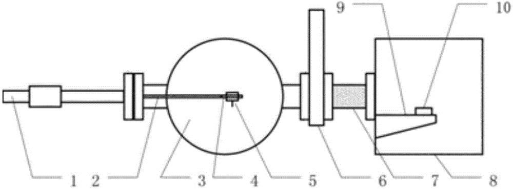
[0036] figure 1 Showing the main technical content of this specific embodiment, this specific embodiment provides a vacuum sample transfer device, which includes: a magnetic rod 1 with a vacuum outer magnetic ring and a vacuum inner magnetic ring, a vacuum chamber 3. The sample transfer rod 2, the sample cup 5 used to carry the vacuum sample, and the vacuum pipeline used to connect the vacuum chamber 3 and the sampling or sample receiving equipment; wherein, the magnetic rod drives the outer magnetic ring of the vacuum to utilize the magnetic force function, it can drive the vacuum inner magnetic ring to move in axial, radial and circumferential directions; the vacuum inner magnetic ring and the sample transfer rod 2 are arranged inside the vacuum chamber, and the The inner magnetic ring is connected, and the front end of the sample transf...


PUM


Abstract

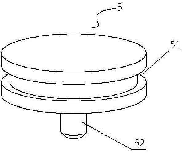
The invention discloses a vacuum sample transfer device which comprises a vacuum cavity, a vacuum pipeline, a magnetic rod, a sample transfer rod and a sample cup, wherein the vacuum pipeline is used for connecting the vacuum cavity and sampling or sample-receiving equipment together; a vacuum valve is arranged on the vacuum pipeline; the magnetic rod comprises a vacuum outer magnetic ring and a vacuum inner magnetic ring; the vacuum outer magnetic ring is located out of the vacuum cavity; the vacuum inner magnetic ring is located in the vacuum cavity; the sample transfer rod is arranged in the vacuum cavity and is connected with the vacuum inner magnetic ring; a Y-shaped sample cup clamp with two branches is arranged at the front end of the sample transfer rod; the sample cup is used for loading a vacuum sample, is of a concave step structure, and is assembled on the sample transfer rod by virtue of the clamping matching between the concave step structure and the two branches; through the design of the Y-shaped sample cup clamp at the front end of the sample transfer rod and the concave step structure of the sample cup, the vacuum sample is stable and reliable in the transferring process; the problem that the sample falls off is not caused; and the vacuum sample transfer device disclosed by the invention is simple in structure, low in cost, and high in universality, and can be applicable to sample chambers and sample stages of different vacuum systems.

Description

technical field [0001] The invention relates to the field of vacuum technology, in particular to a vacuum sample transfer device. Background technique [0002] According to the pressure level, the vacuum is divided into low vacuum, medium vacuum, high vacuum and ultra-high vacuum. Generally speaking, vacuum equipment is composed of vacuum pumps, vacuum gauges, vacuum chambers and other components, combined with vacuum pipes to ensure that a specific vacuum environment is obtained and maintained in a certain space, and to ensure that a certain process or physical process is carried out in the vacuum system. implemented within. [0003] Traditionally, in order to ensure that samples are transferred in a vacuum environment, a vacuum transfer box is usually used for transfer. The vacuum transfer box has good vacuum sealing performance. When operating, first install the vacuum transfer box into the sample cavity, use the sample transfer tool to transfer the sample into the vacu...

Claims


Application Information

Patent Timeline
Patent Type & Authority Applications(China)
IPC IPC(8): G01N35/00
Inventor 张军安耿俊清梁春蕾
Owner KYKY TECH
Learn More