


Quick Research
Generate reliable direction feasibility study reports for your R&D in just a few steps.

Technical Q&A
Discover and master advanced knowledge NOW. Basics, ideas, possibilities, all at once.

Find Solutions
As an expert in R&D theories, this can generate solutions to your technical problems instantly.

Evaluate Feasibility
Analyze your overall solution with one click, know your potential R&D risks in advance.

Monitor Landscape
Get weekly tech updates, stay abreast of the latest tech innovations and key insights.
Charged particle photographing device for parallel matching beams
A technology of charged particles and matching beams, which is applied in the use of radiation for material analysis, etc., can solve problems such as image blur and unfavorable photographic resolution, and achieve the effects of reducing influence, improving resolution, and improving resolution
- Summary
- Abstract
- Description
- Claims
- Application Information
AI Technical Summary
Problems solved by technology
Method used
Image

Examples
Embodiment 1
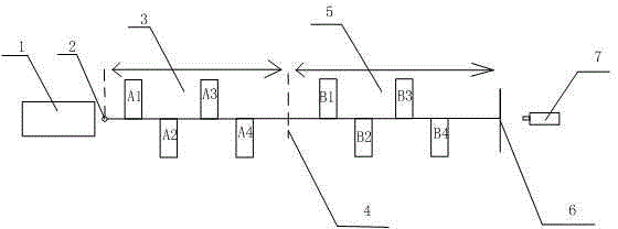
[0024] Such as Figure 1-2 As shown, the present invention includes a beam transmission line and an optical imaging structure. The beam transmission line includes a centrally symmetrical front quadrupole magnet group 3 and a rear quadrupole magnet group 5. The optical imaging structure is located at the end of the beam transmission line, wherein Front segment quadrupole magnet group 3 and rear segment quadrupole magnet group 5 are identical in shape and all comprise four completely identical quadrupole magnets, and on the central symmetrical point of front segment quadrupole magnet group 3 and rear segment quadrupole magnet group 5 The angle collimator 4 is installed, and the transmission matrix of the quadrupole magnet group 3 in the front section adopts a fourth-order matrix M:
[0025] The fourth-order matrix M is to satisfy the parallel beam incident condition: M 11 = 0, M 22 = 0, M 33 = 0, M 44 = 0 of the fourth-order transfer matrix, the front and rear subscripts of ...
Embodiment 2
[0097] This embodiment is preferably as follows on the basis of Embodiment 1: there are two four-stage magnets located above the horizontal axis in the front quadrupole magnet group 3, and the other two four-stage magnets are located below the horizontal axis, and the four-stage magnets located above the horizontal axis and the four-level magnets located below the horizontal axis are alternately arranged at equal intervals along the horizontal direction.
[0098] In this scheme, according to the energy of the charged particle beam used, a quadrupole magnet suitable for the energy is selected; and the distance between the magnets is reasonably set according to the strength of the quadrupole magnet and the size of the site; using the matching function of the software, according to (27)-(30) these four constraints, calculate the strength of the quadrupole magnet. Among them, the four-stage magnets A1 and A3 in the front quadrupole magnet group 3 and the four-stage magnets B1 and ...
PUM
 Abstract
Description
Claims
Application Information
 - R&D Engineer
- R&D Manager
- IP Professional
- Industry Leading Data Capabilities
- Powerful AI technology
- Patent DNA Extraction
Browse by: Latest US Patents, China's latest patents, Technical Efficacy Thesaurus, Application Domain, Technology Topic, Popular Technical Reports.
© 2024 PatSnap. All rights reserved.Legal|Privacy policy|Modern Slavery Act Transparency Statement|Sitemap|About US| Contact US: help@patsnap.com