Bending pipe correction tooling platform and pipe correction method

A technology of pipe bending and platform, applied in the field of pipe bending and pipe calibration tooling platform and pipe calibration, can solve the problems of low accuracy, affecting the deviation of the connection position of pipes, pipes and flanges, and achieve the effect of ensuring consistency and accuracy.

Active Publication Date: 2015-09-16
JIANGSU YANGMING SHIP EQUIP MFG TECH
View PDF8 Cites 15 Cited by
  • Summary
  • Abstract
  • Description
  • Claims
  • Application Information

AI Technical Summary

Problems solved by technology

[0006] (1) The accuracy is not high, and there will be more unqualified;
[0007] (2) The operation time is long, accidents frequently occur during the handling operation, and there are potential safety hazards;
[0008] (3) Auxiliary tools such as flanges and angle irons are required, resulting in waste of materials;
[0009] (4) In the long-distance connection of pipelines, there will be serious position offset installation, which seriously affects the installation design of the entire construction;
[0010] (5) Skilled and experienced professional technicians are required to complete
However, if the above two methods are used, the position of the bolt hole of the manufactured closing pipe is often incorrect, resulting in the situation that it cannot be installed.
In the connection between the flange and the pipe, the uniformity of the gap between the pipe and the flange cannot be controlled; the filling material cannot be uniformly filled during the automatic welding process, resulting in serious deviations in the connection position between the pipe and the flange
These all seriously affect the deviation of long-distance manufacturing and installation of pipelines, and affect the investment, design, efficiency, quality, and safety of the entire project.

Method used


Image

  • Bending pipe correction tooling platform and pipe correction method
  • Bending pipe correction tooling platform and pipe correction method

Examples


Embodiment Construction

[0025] The present invention will be further described below in conjunction with the accompanying drawings.

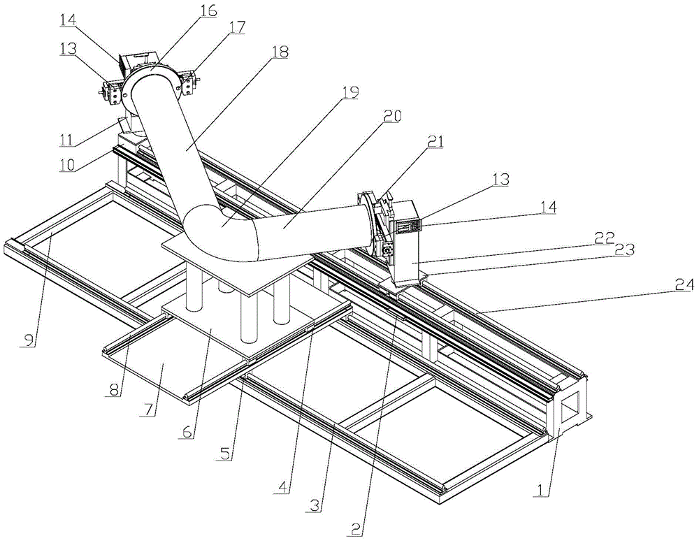
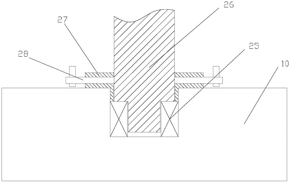
[0026] Such as figure 1 with figure 2As shown, a kind of bent pipe collation tooling platform of the present invention comprises a frame 1, a fixed headstock 11 positioned at one end of the frame 1 and a movable tailstock 22 positioned at the other end of the frame 1, and the curved pipe includes a first Straight pipe 18, the second straight pipe 20 and the elbow 19 connecting the first straight pipe 18 and the second straight pipe 20, a fixed seat 10 is provided between the fixed head frame 11 and the frame 1, and the fixed seat 10 is provided with The first groove, the first bearing 25 is installed in the first groove, the bottom of the fixed head frame 11 is extended with a stepped first rotating shaft 26, the first rotating shaft 26 is sleeved on the first bearing 25, the first rotating shaft The first bearing cover 27 is sleeved on the shaft 26, and the first b...


PUM


Abstract

The invention discloses a bending pipe correction tooling platform and a pipe correction method. The platform comprises a frame, a fixed headstock and a movable tailstock, and is characterized in that a fixed base is arranged between the fixed headstock and the movable tailstock, the fixed base is provided with a first groove, the first groove is internally provided with a first bearing, the bottom part of the fixed headstock is provided with a stepped first rotating shaft, the first rotating shaft is arranged on the first bearing in a sleeved mode, the first rotating shaft is provided with a first bearing cover in a sleeved mode, and the first bearing cover is provided with a first locking device; the frame is provided with a first guide rail and a second guide rail which are parallelly arranged, the movable tailstock is located at the first guide rail and can move along the first guide rail, the first guide rail is provided with a magnetic grating ruler, and the second guide rail is provided with a movable supporting device which supports a bending pipe. According to the invention, an angle of a flange is adjusted conveniently through the rotatable fixed tailstock and the rotatable movable tailstock, the flange is enabled to be attached to both ends of the bending pipe, a horizontal position of the bending pipe and a height position of the flange are guaranteed through a vertical sliding block and a horizontal clamping block, and the bending pipe correction accuracy is ensured.

Description

technical field [0001] The invention relates to a welding device for a bent pipe and a flange, in particular to a bent pipe correction tooling platform and a pipe correction method. Background technique [0002] In the shipping industry, there are pipes everywhere in the ship, and a series of operations such as the design and manufacture of these pipe fittings and the inspection after installation in the ship are called "pipe laying". Usually ships are constructed and installed in sections. When the sections are closed, the pipelines between the sections need to be connected by closing pipes. However, it is impossible to manufacture all kinds of closing pipes only by relying on the pipeline design drawings. The production of closing pipes is usually Adopt type method and field welding method. [0003] The type-taking method is to fix the two flanges to the flanges of the two pipes that need to be connected, then weld the two flanges into a whole with angle iron, transport t...

Claims


Application Information

Patent Timeline
Patent Type & Authority Applications(China)
IPC IPC(8): G01B21/00
CPCB23K37/0536
Inventor 邹家生严铿许祥平高飞叶友利施志强黄晓龙
Owner JIANGSU YANGMING SHIP EQUIP MFG TECH
Why Eureka
Try Eureka