Multi-joint industrial mechanical arm

An industrial manipulator and multi-joint technology, applied in the direction of manipulators, program control manipulators, manufacturing tools, etc., can solve problems such as poor working stability, low service life, and prone to failure, so as to improve service life, high life, and provide accuracy Effect

Inactive Publication Date: 2015-09-16
MICROPAK CNC TECH QUANZHOU
View PDF9 Cites 14 Cited by
  • Summary
  • Abstract
  • Description
  • Claims
  • Application Information

AI Technical Summary

Problems solved by technology

Although the structure of the manipulator is relatively simple, each motor of the manipulator is simply arranged at the end of the connecting arm. When in use, the connecting arm needs to bear a large torque, which is easy to fatigue and fracture, and has a low service life; at the same time, each connection of the manipulator The arms are connected and supported by the corresponding reducer. The reducer needs to bear a large force during work, which affects the stability of its work. In addition, the output shafts of the motors of the manipulator are coaxial with the corresponding connecting arm rotation shafts. , the power lines of each motor and the winding of each line of the control system need to avoid the movement mechanism, the winding is relatively complicated, prone to failure, and the working stability is poor

Method used


Image

  • Multi-joint industrial mechanical arm
  • Multi-joint industrial mechanical arm
  • Multi-joint industrial mechanical arm

Examples


Embodiment Construction

[0046] The present invention will be further described below in conjunction with the accompanying drawings and specific embodiments.

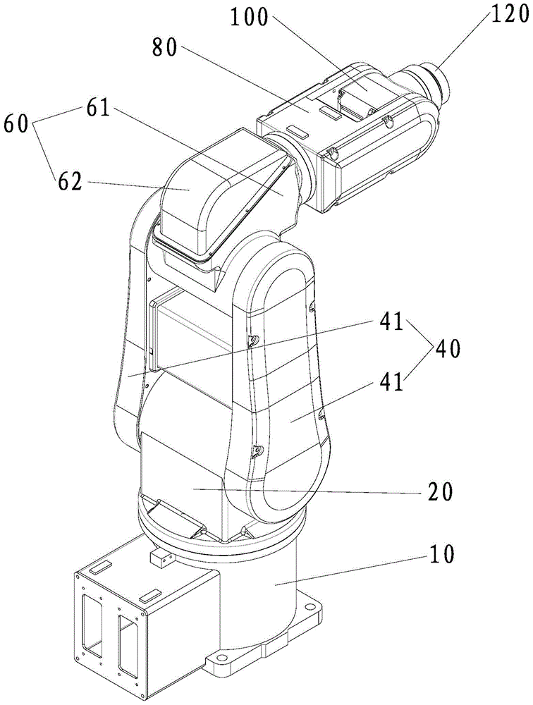
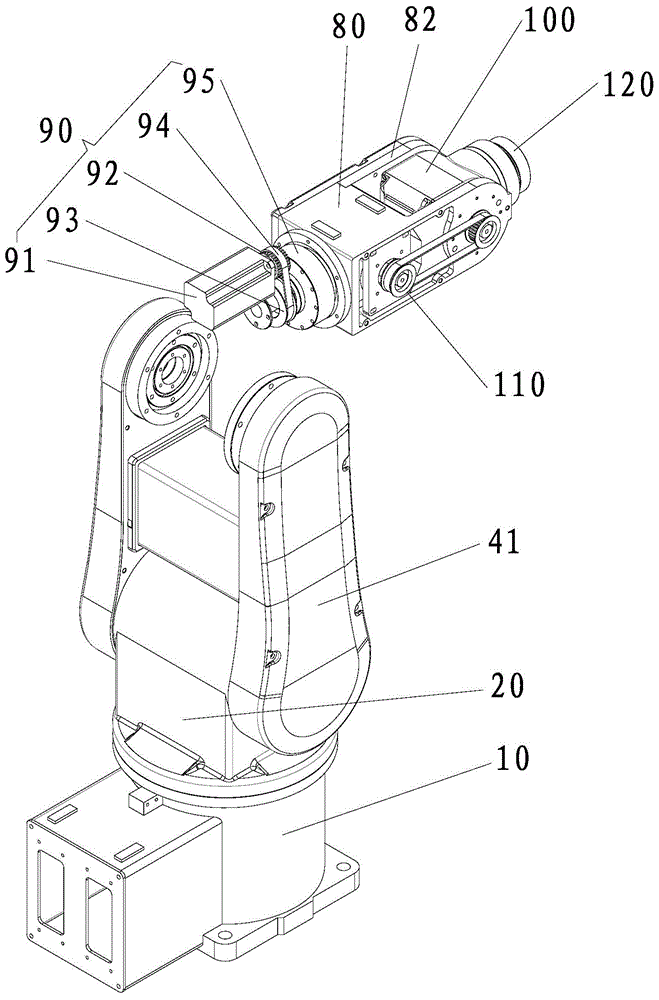
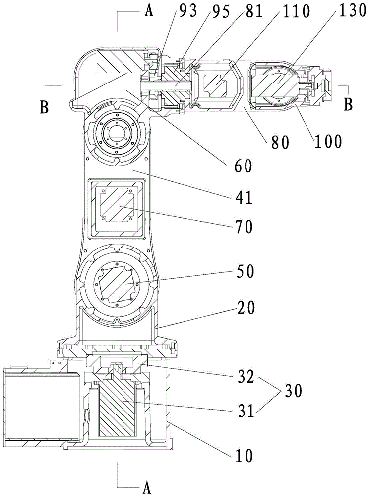
[0047] Such as Figure 1-Figure 5 As shown, the multi-joint industrial manipulator provided in this embodiment includes a base 10 that can be fixed on the bottom plate and a control system for controlling the movement of the entire manipulator. The control system is a conventional system in the art and will not be described in detail here.

[0048]A first joint 20 and a first driving device 30 for driving the first joint 20 to rotate are installed on the base 10 . The first joint 20 is installed on the upper end of the base 10, and the first driving device 30 includes a first motor 31 located inside the base 10 and a first speed reducer 32 connected to the first motor 31, and the output shaft of the first motor 31 Arranged vertically, the output shaft of the first reducer 32 is coaxial with the output shaft of the first motor 31, and the first...


PUM


Abstract

The invention provides a multi-joint industrial mechanical arm. The multi-joint industrial mechanical arm comprises a base, a first joint and a first driving device are installed at the upper end of the base, two swinging arms and a swinging driving device are installed on the first joint, a second joint and a second driving device are installed on the swinging arms, and the swinging driving device comprises a swinging motor fixed to the upper end of the first joint and located between the two swinging arms. One end of the second joint is connected to the upper ends of the two swinging arms in a rotating mode and located between the two swinging arms, and the second driving device comprises a second motor which is located between the two swinging arms and is close to the swinging motor. Through arranging the two swinging arms, torsion transferred by the joints is distributed to the two swinging arms, meanwhile, the gravity center of the swinging motor and the gravity center of the second motor are low according to the arrangement positions, the torsion borne by the swinging arms is effectively lowered, the structure is simple, the service life is long, and working stability is good.

Description

technical field [0001] The invention relates to a manipulator structure, in particular to a multi-joint industrial manipulator. Background technique [0002] The widespread use of industrial robots in industrial manufacturing and processing enterprises is the future development trend. The application of industrial robots can not only improve the output and quality of products, but also play an important role in ensuring personal safety, improving the working environment, reducing labor intensity and increasing productivity. . [0003] Mechanical structure is a key technology to improve the performance of industrial manipulators, which directly affects the stability and accuracy of industrial manipulators. The structure of existing industrial manipulators is generally relatively complex, resulting in relatively complex control systems and high costs. [0004] Chinese invention patent ZL201510055999.4 discloses a new six-degree-of-freedom manipulator, including a base, a fir...

Claims


Application Information

Patent Timeline
Patent Type & Authority Applications(China)
IPC IPC(8): B25J9/06
Inventor 蔡伟强
Owner MICROPAK CNC TECH QUANZHOU
Why Eureka
Try Eureka