Flowing oil production demonstration model

A technology of oil sand and display screen, applied in the field of model, can solve the problem of not obvious and intuitive phenomenon, and achieve the effect of convenient operation, simple principle and accurate simulation value

Inactive Publication Date: 2015-09-09
LIAONING UNIVERSITY OF PETROLEUM AND CHEMICAL TECHNOLOGY
View PDF7 Cites 0 Cited by
  • Summary
  • Abstract
  • Description
  • Claims
  • Application Information

AI Technical Summary

Problems solved by technology

However, there is currently no demonstration model that can simultaneously simulate and demonstrate the impact of changing formation pressure, formation temperature, and gas cap on self-injection oil recovery, and can record the oil production time, and the phenomenon is still not obvious and intuitive in the existing models

Method used


Image

  • Flowing oil production demonstration model

Examples


Embodiment Construction

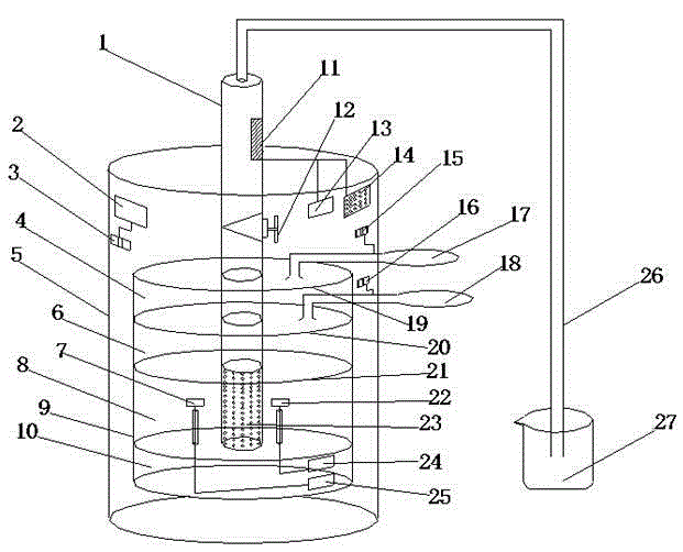
[0009] The present invention is composed of oil well casing (1), simulated temperature display screen (2), temperature adjustment switch (3), air bag 1 (4), temperature control box (5), air bag 2 (6), temperature sensor (7) , oil sand (8), glass cylinder (9), rock layer (10), liquid sensing device (11), control valve (12), timing device (13), LED light (14), air pump 1 control switch ( 15), air pump 2 control switch (16), air pump 1 (17), air pump 2 (18), sealing hole partition 1 (19), sealing hole partition 2 (20), sealing hole partition 3 ( 21), pressure sensor (22), hole (23), pressure display (24), actual temperature display (25), oil pipe (26), oil receiving device (27). During the demonstration, the start of the self-injection process is controlled by controlling the switch of the control valve (12); the oil produced by the self-injection flows into the oil receiving device (27) through the oil pipe (26); when the model passes the self-injection When the extracted oil p...


PUM


Abstract

A flowing oil production demonstration model is composed of the components of an oil well sleeve, a simulated temperature display screen, a temperature adjusting switch, an airbag 1, a control box, an airbag 2, a temperature sensor, oil sand, a glass cylinder, a rock layer, a liquid induction device, a control valve, a timing device, an LED lamp, a first air pump control switch, a second air pump control switch, an air pump 1, an air pump 2, a first sealing porous baffle plate, a second sealing porous baffle plate, a third sealing porous baffle plate, a pressure sensor, holes, a pressure display screen, an oil pipe and an oil receiving device. The flowing oil production demonstration model has advantages of simple principle, convenient operation and accurate simulated number. The flowing oil production demonstration model can clearly and visually demonstrate system structure of a flowing oil well and principle and phenomenon of flowing oil production. The flowing oil production demonstration model is particularly suitable for demonstration in teaching.

Description

technical field [0001] The invention relates to a model, in particular to a self-spraying oil recovery demonstration model. Background technique [0002] Various teaching demonstration models bring a lot of convenience to students and can help students understand various phenomena and their principles. However, there is currently no demonstration model that can simultaneously simulate and demonstrate the impact of changing formation pressure, formation temperature, and gas cap on self-injection oil recovery, and can record the oil production time, and the phenomenon is still not obvious and intuitive in the existing models. Therefore, aiming at the phenomenon of self-flowing wells, it is particularly necessary to design a demonstration model of self-flowing oil recovery that simultaneously simulates the influence of various factors on self-flowing oil recovery and records the oil production time. Contents of the invention [0003] In view of the above problems, the presen...

Claims


Application Information

Patent Timeline
Patent Type & Authority Applications(China)
IPC IPC(8): G09B25/02
CPCG09B25/02
Inventor 赵宏宇李沼萱王旭秦永航潘一杨双春王诗雨雒旭
Owner LIAONING UNIVERSITY OF PETROLEUM AND CHEMICAL TECHNOLOGY
Why Eureka
Try Eureka