
Pressure sensing structure, electronic equipment border and mobile electronic equipment

A pressure and sensor technology, applied in electrical digital data processing, instruments, digital data processing parts, etc., can solve the problems of large thickness space, increase production cost, occupy products, etc., to save thickness space and reduce installation difficulty. Effect

Active Publication Date: 2015-09-09
SHENZHEN NEW DEGREE TECH
View PDF6 Cites 1 Cited by
  • Summary
  • Abstract
  • Description
  • Claims
  • Application Information

AI Technical Summary

Problems solved by technology

[0004] First of all, in the usual pressure touch technology, the pressure sensor is installed on the back of the pressing surface. Since the sides of thinner electronic products are relatively long and narrow, and the touch sensing device connected to the back of the touch surface has a large size, this will occupy a larger area of ​​the product. thickness space; moreover, to install the pressure sensing device on the back of the relatively long and narrow surface, the process requirements are high, which will increase the production cost
[0005] Secondly, when the force user presses on the relatively narrow side, the deformation of the pressing surface along the direction of force application is smaller than that of pressing on the relatively wide front surface along the direction of force application, especially when pressing near the edge The deformation of the area is very small, and it is difficult to obtain effective pressure information only by the pressure sensor installed on the back of the pressing surface;

Method used


Image

  • Pressure sensing structure, electronic equipment border and mobile electronic equipment
  • Pressure sensing structure, electronic equipment border and mobile electronic equipment
  • Pressure sensing structure, electronic equipment border and mobile electronic equipment

Examples


Embodiment Construction

[0030] In order to fully understand the technical content of the present invention, the technical solution of the present invention will be further introduced and illustrated below in conjunction with specific embodiments.

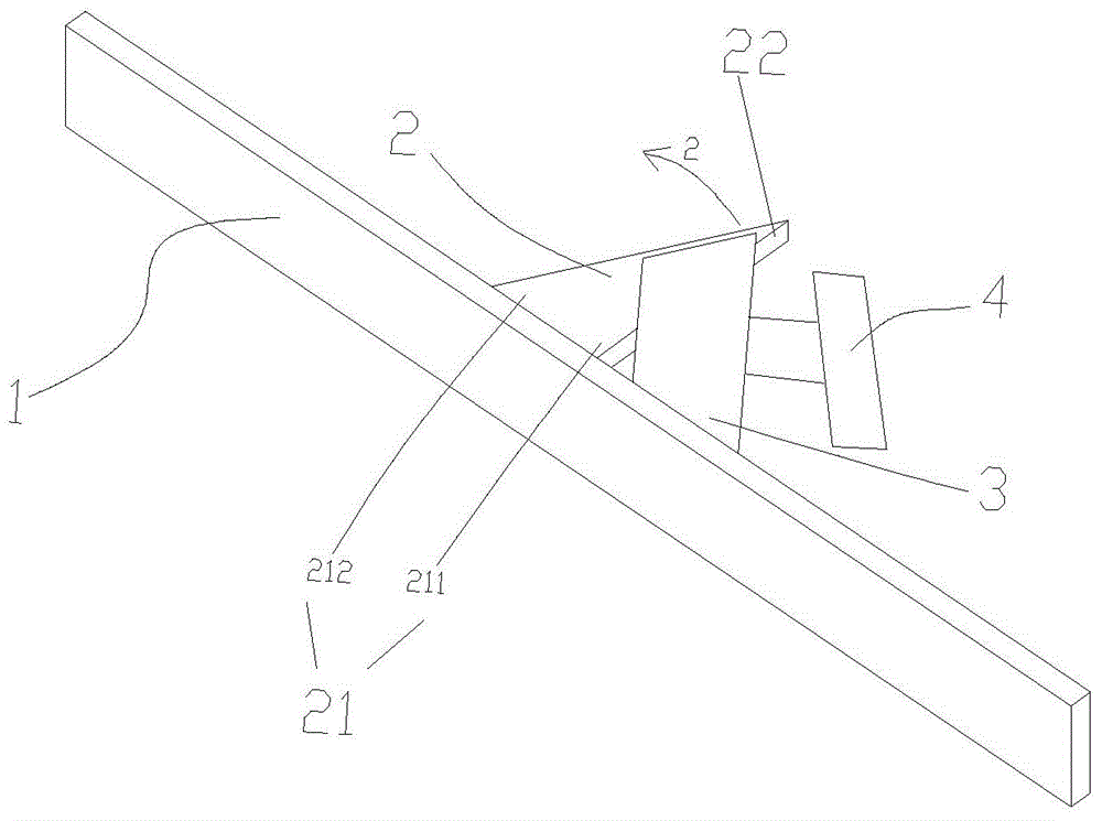
[0031] Such as figure 1 As shown, the structural schematic diagram of the first embodiment of the pressure sensing structure, the pressure sensing structure includes an operation panel 1 for the force applicator to apply pressure, and the arrow 1 indicates the position and direction of the force application; the deformation amplification component includes two mutual Independent rectangular connectors 2, the two connectors 2 are perpendicular to the back of the operation panel 1 and can be integrally formed with the operation panel 1; at the same time, the connectors 2 can also be connected with the operation panel 1 by welding, riveting and other mechanical connections; induction The unit includes a pressure sensor 3 and a control circuit 4 , the pressure...


PUM


Abstract

The present invention relates to a pressure sensing structure, an electronic equipment border and mobile electronic equipment. The pressure sensing structure comprises an operation panel, a deformation amplification part and a sensing unit, wherein the operation panel is used for allowing a force applier to apply force; after the force applier applies pressure to the operation panel, small physical deformation is generated, wherein the small physical deformation can generate relatively large physical deformation through deformation amplification part; the sensing unit is used for converting the physical deformation generated by the deformation amplification part into an electric signal for outputting; one end of the deformation amplification part is fixedly connected to the back surface of the operation panel and corresponds to a force-receiving part of the front surface of the operation panel, and the other end of the deformation amplification part is connected with the sensing unit. According to the invention, a pressure sensor does not need to be directly mounted on the relatively narrow back surface of the force-applying surface, so that the thickness space of the electronic equipment is reduced and the manufacturing difficulty is lowered.

Description

technical field [0001] The invention relates to the technical field of electronic equipment, in particular to a pressure sensing structure, a frame of an electronic equipment and a mobile electronic equipment. Background technique [0002] Currently, the touch button technology has begun to be more and more widely used in electronic products and wearable devices. The existing technologies can be mainly divided into resistance strain gauge type, capacitive sensing type and piezoelectric ceramic type, which can be applied to buttons or touch screens of various home appliances, handheld electronic products and wearable devices. This technology of directly integrating buttons or touch screens on the pressing surface has great advantages over traditional mechanical buttons. The main difference is that traditional mechanical buttons are easy to wear, loosen, and harden after a long period of use. , not waterproof, not dustproof, not oil-proof; and the touch button does not have t...

Claims


Application Information

Patent Timeline
IPC IPC(8): G06F1/16
Inventor 李灏
Owner SHENZHEN NEW DEGREE TECH
Learn More