Pressure generation device and generation method

A technology of generating device and pressure, applied in hydroelectric power generation, fluid pressure converter, machine/engine, etc., can solve the problems of large volume, large disturbance noise, complex manufacturing process, etc.

Active Publication Date: 2015-09-02
林中尉
View PDF7 Cites 1 Cited by
  • Summary
  • Abstract
  • Description
  • Claims
  • Application Information

AI Technical Summary

Problems solved by technology

At the same time, the disturbance noise is very large when the propeller rotates. For these thrust generating devices, the volume is large, the noise is large, the manufacturing process is complicated, and the cost is high.

Method used


Image

  • Pressure generation device and generation method
  • Pressure generation device and generation method

Examples


Embodiment 1

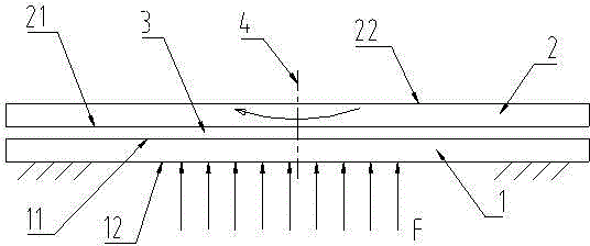
[0019] see figure 1 The shown pressure generating device includes a fixed part 1 and a moving part 2, both of which are discs, and the two discs are coaxial. The inner surface 21 of the movable part is opposite to the inner surface 11 of the fixed part up and down, and there is lubricating oil in the gap 3 between the two opposite inner surfaces, and the width of the gap 3 is less than 0.5mm. A driving mechanism (not shown) for driving the movable member to rotate relative to the fixed member around the fixed member axis 4 is connected to the movable member. During the rotation of the movable member 2, the width of the gap 3 remains substantially constant. The fixed part 1 and the moving part 2 are placed in the air, and the outer surface 22 of the moving part and the outer surface 12 of the fixed part are both in contact with the air. When the moving part rotates relative to the fixed part, since the gap 3 is very small, the force of the lubricating oil on the inner surface...

Embodiment 2

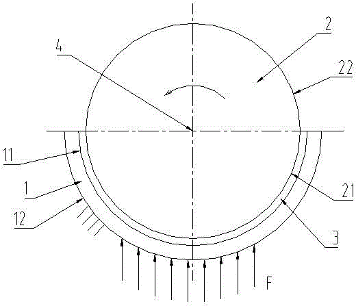
[0023] see figure 1 The pressure generating device shown includes a fixed part 1 and a moving part 2, the fixed part 1 is a half ring, the moving part 2 is a shaft, and the half ring is coaxial with the shaft (the axis coincides). The inner surface 21 of the movable part is opposite to the inner surface 11 of the fixed part up and down, and there is lubricating oil in the gap 3 between the two opposite inner surfaces, and the width of the gap 3 is less than 0.5mm. A driving mechanism (not shown) for driving the movable member to rotate relative to the fixed member around the fixed member axis 4 is connected to the movable member. During the rotation of the movable member 2, the width of the gap 3 remains substantially constant. The fixed part 1 and the moving part 2 are placed in water, and the outer surface 22 of the moving part and the outer surface 12 of the fixing part are both in contact with the water. When the moving part rotates relative to the fixed part, since the ...


PUM


Abstract

The invention provides a pressure generation device which is simple in structure, compact in size, small in noise and convenient to produce. The pressure generation device comprises a fixed element arranged in a fluid and a moving element moving relative to the fixed element, wherein the opposite inner side surfaces of the moving element and the fixed element are contacted or smaller gap is formed between the opposite inner side surfaces of the moving element and the fixed element, and the outer side surfaces of the moving element and the fixed element are both contacted with the fluid. The invention further provides a pressure generation method which is easy to implement and produces small noise. When the moving element moves relative to the fixed element, the action force, applied by the fluid on the outer side surface of the moving element, on the moving element is smaller than the action force, applied by the fluid on the outer side surface of the fixed element, on the fixed element, so that the fluid can generate pressure on the pressure generation device.

Description

technical field [0001] This patent relates to a pressure (or thrust) generating device and a generating method for generating pressure (or thrust). Background technique [0002] For the propeller of a helicopter or the propeller of a ship, in order to generate greater thrust, the area of ​​the blade needs to be large enough. For this reason, the propeller is often made very long to increase the thrust. At the same time, the disturbance noise is very large when the propeller rotates. For these thrust generating devices, the volume is large, the noise is large, the manufacturing process is complicated, and the cost is high. Contents of the invention [0003] The purpose of the present invention is to provide a pressure generating device with simple structure, small volume, low noise and convenient preparation. [0004] The pressure generating device of the present invention comprises a fixed part located in the fluid, a moving part that moves relative to the fixed part, the...

Claims


Application Information

Patent Timeline
Patent Type & Authority Applications(China)
IPC IPC(8): F15B3/00
CPCF15B3/00F03B3/00Y02E10/20
Inventor 林中尉
Owner 林中尉
Why Eureka
Try Eureka