reciprocating piston engine

A technology of reciprocating piston and piston mechanism, which is applied in the open gas positive displacement engine factory and other directions

Active Publication Date: 2016-10-05
山东福瑞斯动力科技有限公司
View PDF6 Cites 0 Cited by
  • Summary
  • Abstract
  • Description
  • Claims
  • Application Information

AI Technical Summary

Problems solved by technology

[0002] The efficiency problems and pollution emission problems of volumetric power mechanisms represented by gasoline engines and diesel engines have not been well resolved. The fundamental reason is that their timing combustion methods and the volume changes in the compression process and expansion process are the same. These two major problems are caused by the basic structure of this type of engine, which cannot be changed, so a new type of engine needs to be invented

Method used


Image

  • reciprocating piston engine
  • reciprocating piston engine
  • reciprocating piston engine

Examples


Embodiment 1

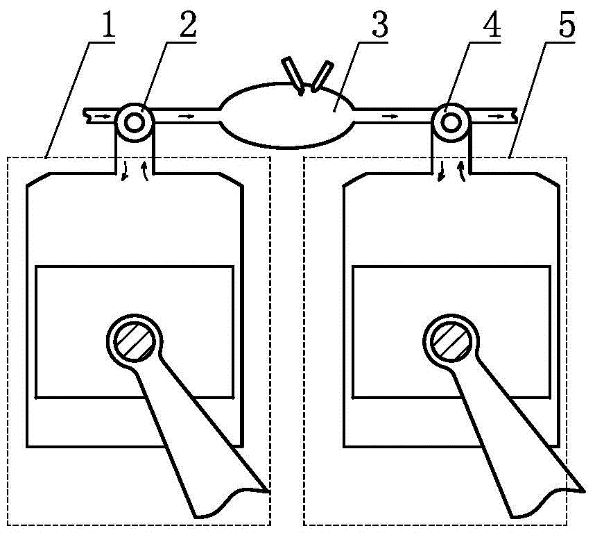
[0045] A reciprocating piston mechanism engine, such as figure 1 As shown, it includes a reciprocating cylinder-piston mechanism 1 for compression, a gas compression rotary control valve 2, a continuous working medium heater 3, a gas expansion rotary control valve 4, and a reciprocating cylinder-piston mechanism 5 for expansion. The gas compression rotary control valve 2 and The reciprocating cylinder-piston mechanism 1 for compression is correspondingly arranged to form a part of the reciprocating piston rotary valve compression unit, and the gas expansion rotary control valve 4 is correspondingly arranged to form a part of the reciprocating piston rotary valve expansion unit with the reciprocating cylinder-piston mechanism 5 for expansion. , the working medium outlet of the reciprocating piston rotary valve compression unit communicates with the working medium inlet of the reciprocating piston rotary valve expansion unit through the working medium continuous heater 3, and the...

Embodiment 2

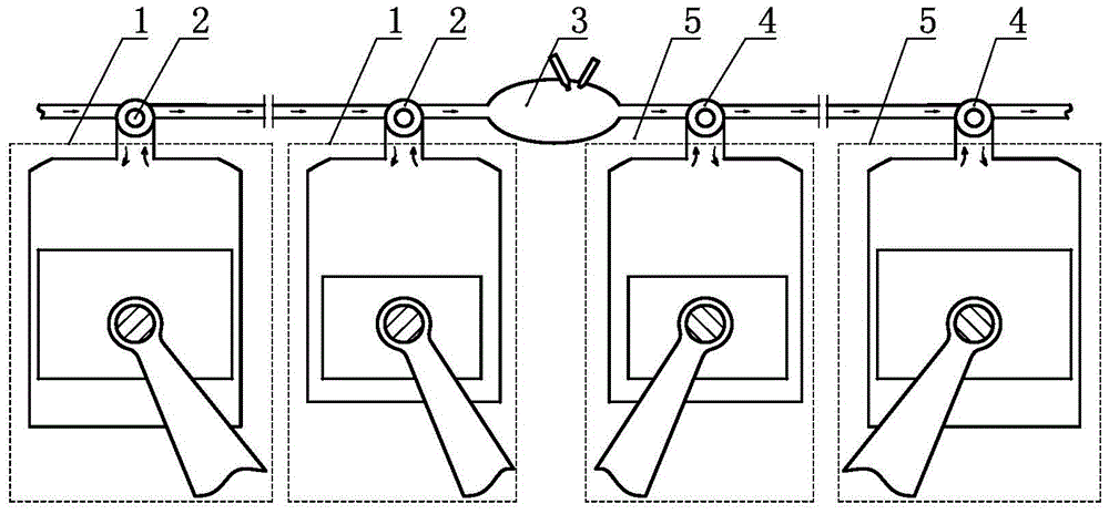
[0050] A reciprocating piston mechanism engine, such as figure 2 As shown, on the basis of Embodiment 1, there are more than two reciprocating piston rotary valve compression units with different displacements, and all the reciprocating piston rotary valve compression units are connected in sequence from large to small in displacement. All the reciprocating piston rotary valve compression units are connected in descending order of displacement, and the working medium outlet of the reciprocating piston rotary valve compression unit with the smallest displacement is connected with the continuous working medium heater 3 . Preferably, there are more than two reciprocating piston rotary valve expansion units with different displacements, all the reciprocating piston rotary valve expansion units are connected in sequence from small to large displacement, and the reciprocating piston rotary valve with the smallest displacement The working fluid inlet of the expansion unit communicat...

Embodiment 3

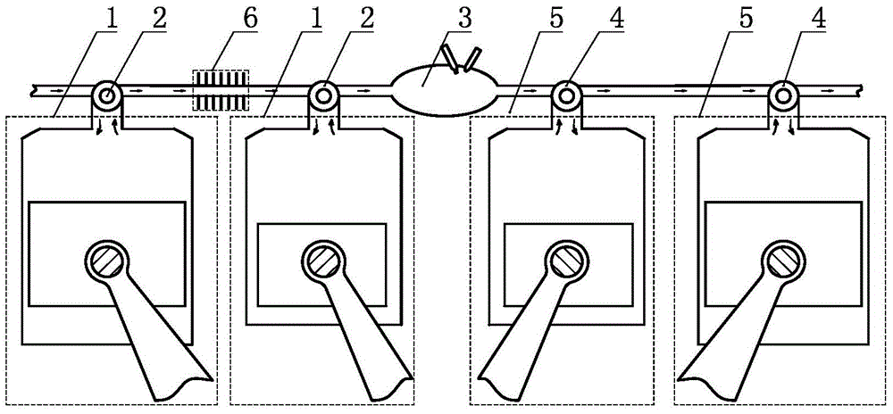
[0053] A reciprocating piston mechanism engine, such as image 3 As shown, on the basis of Embodiment 2, a cooler 6 is arranged in series between at least two adjacent reciprocating piston rotary valve compression units.

[0054] As a changeable implementation manner, embodiment 1 and embodiment 2 and their changeable implementation manners can further have a cooler 6 arranged in series between at least two adjacent reciprocating piston rotary valve compression units.


PUM


Abstract

The invention discloses a reciprocating piston mechanism engine. The reciprocating piston mechanism engine comprises a reciprocating cylinder piston mechanism for compression, a gas compression and rotation control valve, a continuous working-medium heater, a gas expansion and rotation control valve and a reciprocating cylinder piston mechanism for expansion. The gas compression and rotation control valve and the reciprocating cylinder piston mechanism for compression are arranged correspondingly to constitute a part of a reciprocating piston rotation valve compression unit, the gas expansion and rotation control valve and the reciprocating cylinder piston mechanism for expansion are correspondingly arranged to form a part of a reciprocating piston rotation valve expansion unit, a working-medium outlet of the reciprocating piston rotation valve compression unit is communicated with a working-medium inlet of the reciprocating piston rotation valve expansion unit via the continuous working-medium heater, the ratio of the volume of the working-medium inlet of the reciprocating piston rotation valve expansion unit to that of the working-medium outlet of the reciprocating piston rotation valve compression unit is larger than one. The reciprocating piston mechanism engine is few in parts, low in cost, stable in operation and few in pollutant emission, has high power density and efficiency and can be applied to various fuels.

Description

technical field [0001] The invention relates to the field of thermal energy and power, in particular to a reciprocating piston mechanism engine. Background technique [0002] The efficiency problems and pollution emission problems of volumetric power mechanisms represented by gasoline engines and diesel engines have not been well resolved. The fundamental reason is that their timing combustion methods and the volume changes in the compression process and expansion process are the same. These two major problems are caused by the basic structure of this type of engine, which cannot be changed, so a new type of engine needs to be invented. Contents of the invention [0003] In order to solve the above problems, the technical scheme proposed by the present invention is as follows: [0004] Scheme 1: The present invention provides a reciprocating piston mechanism engine, comprising a reciprocating cylinder-piston mechanism for compression, a gas compression rotary control valv...

Claims


Application Information

Patent Timeline
Patent Type & Authority Patents(China)
IPC IPC(8): F02G1/02
CPCF02G1/02
Inventor 靳北彪
Owner 山东福瑞斯动力科技有限公司
Why Eureka
Try Eureka