Telescopic evacuation platform stair for subway tunnel interval

An evacuation platform and telescopic technology, applied in mobile stairs, stairs, safety devices, etc., can solve the problems of destroying the continuity of the evacuation platform, affecting the installation and construction of the interval pipeline, affecting the evacuation efficiency, etc., and achieving good access and evacuation effect. , Easy installation and post-maintenance, compact overall structure

Active Publication Date: 2015-09-02
CHINA RAILWAY SIYUAN SURVEY & DESIGN GRP
View PDF7 Cites 4 Cited by
  • Summary
  • Abstract
  • Description
  • Claims
  • Application Information

AI Technical Summary

Problems solved by technology

[0004] However, further studies have shown that this type of existing evacuation platform setting method still has the following defects or deficiencies: first, the height between the evacuation platform and the ballast bed surface is generally about 1000mm, and the contact point between the evacuation platform and the ballast bed is also There are few evacuation stairs, and a large number of evacuated people need to jump directly from the evacuation platform to the landing platform, which can easily cause people to fall and seriously affect the evacuation efficiency; secondly, even if the evacuated people successfully reach the landing platform, it is still difficult to go up to the evacuation platform , so as to evacuate to the adjacent tunnel through the communication channel; finally, if more fixed evacuation stairs are added, not only will the continuity of the evacuation platform be destroyed, there will be safety hazards of evacuees falling from the side door of the vehicle to the disconnected part of the platform, and it may also The shadow intrudes into the boundary of the equipment in the interval, and at the same time affects the installation and construction of the pipeline in the interval

Method used


Image

  • Telescopic evacuation platform stair for subway tunnel interval
  • Telescopic evacuation platform stair for subway tunnel interval
  • Telescopic evacuation platform stair for subway tunnel interval

Examples


Embodiment Construction

[0026] In order to make the object, technical solution and advantages of the present invention clearer, the present invention will be further described in detail below in conjunction with the accompanying drawings and embodiments. It should be understood that the specific embodiments described here are only used to explain the present invention, not to limit the present invention. In addition, the technical features involved in the various embodiments of the present invention described below can be combined with each other as long as they do not constitute a conflict with each other.

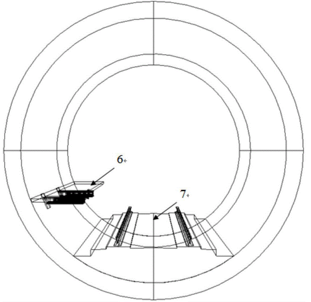
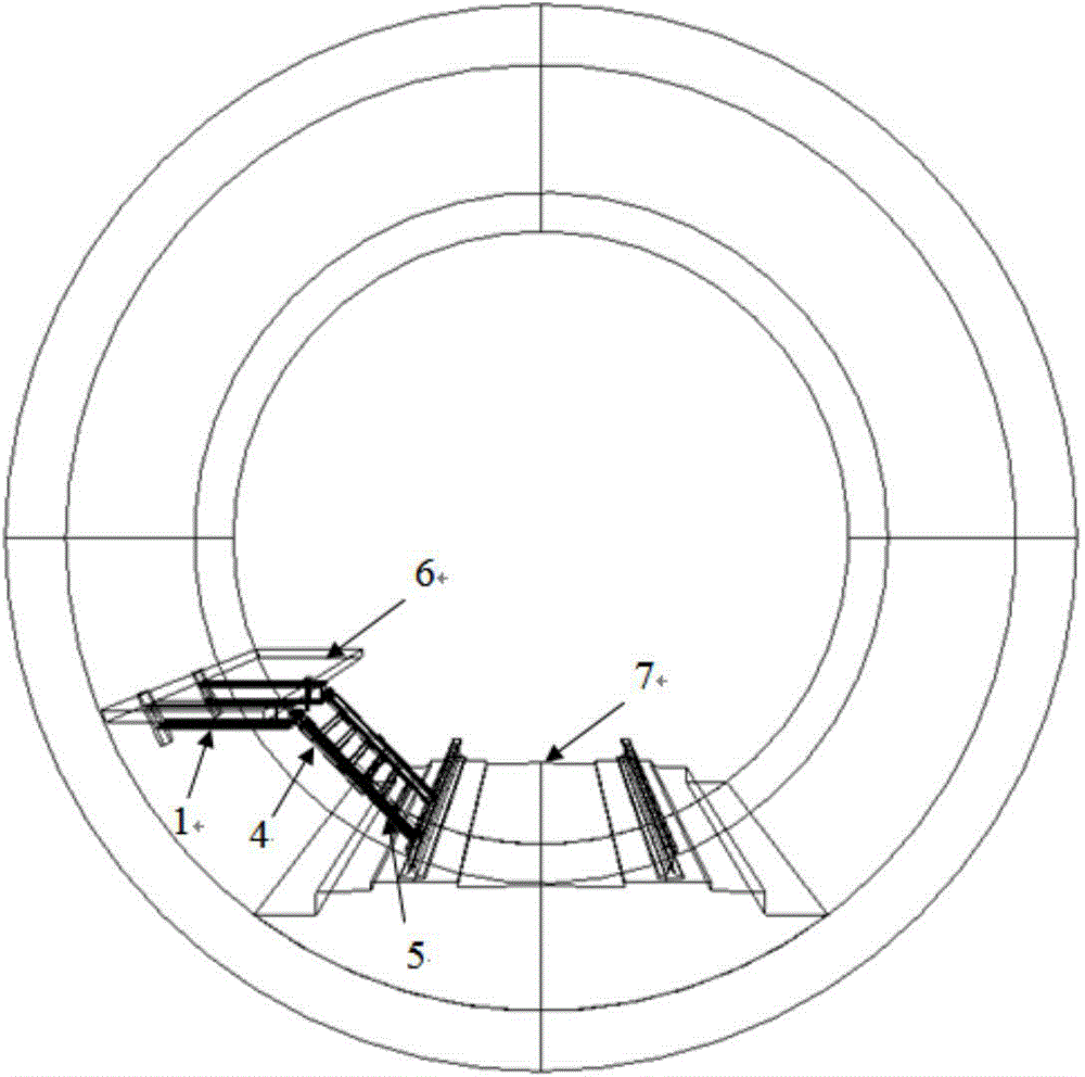
[0027] Figure 4 It is a schematic diagram of the overall structure of the telescopic evacuation platform staircase according to the present invention under normal working conditions, Figure 5 It is a schematic diagram of the overall structure of the telescopic evacuation platform staircase in the evacuation working condition according to the present invention. Such as Figure 4 and Figure...


PUM


Abstract

The invention discloses a telescopic evacuation platform stair for a subway tunnel interval. The telescopic evacuation platform stair comprises a platform main beam and a telescopic stair body, wherein the platform main beam is fixed below an evacuation platform on the subway tunnel interval side, and sliding grooves serving as sliding rails of the stair body are formed in inner sides of the platform main beam respectively; the telescopic stair body comprises a main stair body and an auxiliary stair body, the main stair body and the auxiliary stair body adopt a mutually reverse buckling structure and can be mutually connected in a relative sliding manner, and one end of each of two side edges of the main stair body is connected with sliding blocks in the corresponding sliding groove through a rotary shaft. The telescopic evacuation platform stair for the subway tunnel interval does not intrude a limit of interval equipment under a normal work condition, does not influence mounting of an interval pipeline and has the advantages of convenience in use, safety, reliability, high evacuation efficiency and the like under a using condition.

Description

technical field [0001] The invention belongs to the related technical field of subway rescue equipment, and more specifically relates to a telescopic evacuation platform staircase used in a subway tunnel section. Background technique [0002] With the advancement of my country's urbanization process, the population size and traffic flow in each city have increased sharply, and the pressure on urban traffic is increasing. In order to save land resources, the construction of large-scale underground road tunnels and rail transit has also entered a stage of rapid development. However, due to fires, vehicle or other equipment failures, etc., the subway may stop in non-platform areas such as tunnel sections, which is extremely inconvenient for people to get on and off the vehicle, and it is difficult to evacuate passengers on the vehicle in a timely and safe manner. [0003] Aiming at the evacuation problem of the subway tunnel section, according to the evacuation path in the pri...

Claims


Application Information

Patent Timeline
Patent Type & Authority Applications(China)
IPC IPC(8): E21F11/00E04F11/06
Inventor 廖永亮缪东张浩黄小钢肖俊周小斌杨铭舒冬杨清林王俊代刚李亚强邱海波
Owner CHINA RAILWAY SIYUAN SURVEY & DESIGN GRP
Why Eureka
Try Eureka