Vehicle control device

A technology of control devices and camera devices, applied in optical observation devices, vehicle parts, transportation and packaging, etc., can solve problems such as decreased accuracy, lane recognition or parking frame accuracy

Active Publication Date: 2018-01-23
CLARION CO LTD
View PDF6 Cites 0 Cited by
  • Summary
  • Abstract
  • Description
  • Claims
  • Application Information

AI Technical Summary

Problems solved by technology

In such technologies, when raindrops or dirt adhere to the imaging device (camera), the accuracy of white line recognition in lanes or parking lots decreases, and furthermore, the accuracy of lane recognition or parking frame detection decreases.

Method used


Image

  • Vehicle control device
  • Vehicle control device
  • Vehicle control device

Examples


Embodiment Construction

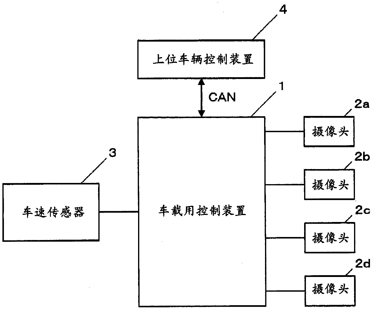
[0027] figure 1 It is a block diagram showing the vehicle-mounted control device 1 according to one embodiment of the present invention. figure 1 The illustrated vehicle-mounted control device 1 is used mounted on a vehicle, and is connected to cameras 2 a , 2 b , 2 c , and 2 d and a vehicle speed sensor 3 . Furthermore, it is connected to a high-level high-level vehicle control device 4 via a CAN (Controller Area Network, controller area network).

[0028] The cameras 2 a to 2 d are composed of, for example, imaging elements such as CCD or CMOS, peripheral circuits, optical lenses, and the like, and are installed on various parts such as the body, bumper, and rearview mirror of the vehicle. These cameras 2a to 2d are called imaging devices.

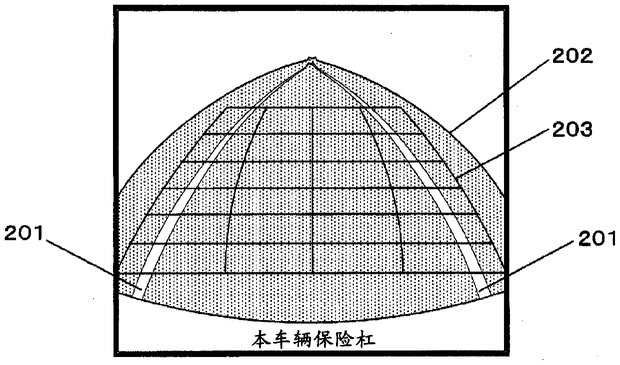
[0029] The cameras 2a to 2d take images (photographs) of the surroundings of the vehicle in different imaging ranges. The imaging ranges of these respective cameras are determined so as to cover the entire periphery of the vehicle in ...


PUM


Abstract

The vehicle-mounted control device includes: an image acquisition unit that acquires an image captured by an imaging device that captures images of the surroundings of the vehicle; a determination range division unit that divides a predetermined determination range of the imaging range of the imaging device into a plurality of regions; an extracting section that extracts feature points having predetermined characteristics around the vehicle from the images acquired by the image acquiring section; The area where the feature points extracted by the extraction unit are accumulated scores; and the determination unit is configured to determine foreign matter adhesion of the imaging device based on the accumulated score results of a plurality of areas.

Description

technical field [0001] The present invention relates to an in-vehicle control device that is mounted on a vehicle and performs foreign matter adhesion determination in an imaging device that captures images around the vehicle. Background technique [0002] Conventionally, there is known a technique of recognizing white lines of a lane or a parking lot using an image captured by an imaging device (camera) mounted on a vehicle, and applying the recognition result to lane recognition or parking frame detection. . In such a technique, when raindrops or dirt adhere to the imaging device (camera), the accuracy of white line recognition of a lane or a parking lot decreases, and furthermore, the accuracy of lane recognition or parking frame detection decreases. Therefore, various methods of detecting attachment of raindrops, dirt, etc. to an imaging device (camera) are proposed (Patent Document 1). [0003] prior art literature [0004] patent documents [0005] Patent Document ...

Claims


Application Information

Patent Timeline
Patent Type & Authority Patents(China)
IPC IPC(8): H04N5/225B60R21/00G03B15/00G08G1/16
CPCB62D15/028B62D15/0285H04N23/811G06V20/588B60R1/00G06T7/20
Inventor 竹村雅幸绪方健人伊藤哲司
Owner CLARION CO LTD
Why Eureka
Try Eureka