
Air conditioner indoor unit and method for controlling the same

A technology for air conditioners and indoor units, which is applied in air conditioning systems, airflow control components, heating and ventilation control systems, etc., and can solve the problems of limited adjustment range of air guiding effects, etc., and achieves an increase in design freedom and a wide range of air guiding Effect

Inactive Publication Date: 2015-08-26
DAIKIN IND LTD
View PDF9 Cites 1 Cited by
  • Summary
  • Abstract
  • Description
  • Claims
  • Application Information

AI Technical Summary

Problems solved by technology

thus, Figure 5 In the indoor unit of the air conditioner shown in the prior art, the adjustment range for the air guiding effect is limited

Method used


Image

  • Air conditioner indoor unit and method for controlling the same
  • Air conditioner indoor unit and method for controlling the same
  • Air conditioner indoor unit and method for controlling the same

Examples


no. 1 example

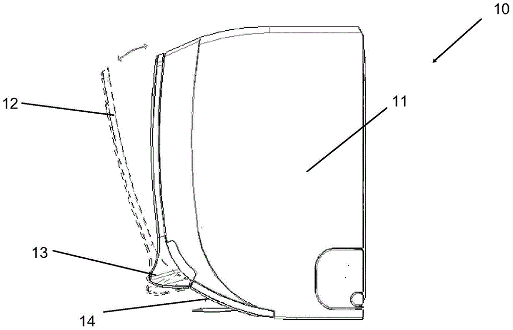
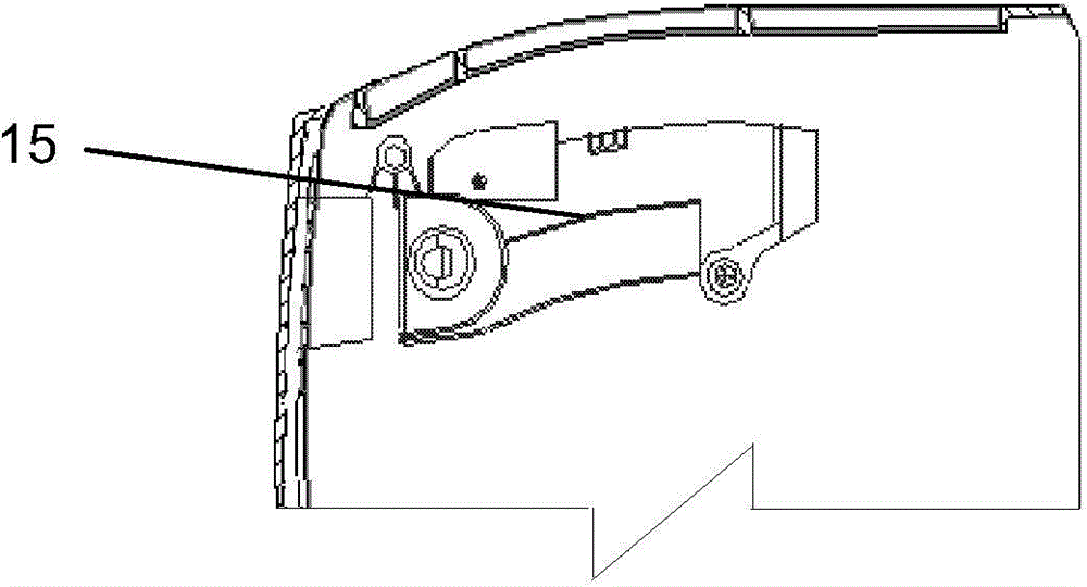
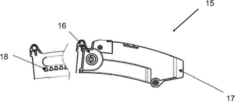
[0045] figure 1 A side view of a first embodiment of the air conditioner indoor unit 10 of the present invention is shown. Such as figure 1 As shown, a front panel 12 is installed on the main body 11 of the indoor unit of the air conditioner, and a wind guide panel 13 is formed at the bottom of the front panel 12 . exist figure 1 In the shown first embodiment, the wind guide panel 13 is integrally formed on the front panel 12 . An air outlet 14 is provided under the front panel 12 . Specifically, the air outlet 14 is arranged so that the air guide panel 13 is located on the upper part of the air outlet 14 , so as to have a guiding effect on the airflow flowing out of the air outlet 14 .

[0046] In the first embodiment of the present invention, the front panel 12 is movably mounted on the main body 11 of the indoor unit 10 of the air conditioner so as to be movable between a closed position shown by solid lines and an open position shown by dotted lines. exist figure...

no. 2 example

[0053] Figure 4 A second embodiment of the invention is shown. For the sake of brevity, only the parts of the second embodiment that are different from the first embodiment will be described below, and the parts of the second embodiment that are the same as those of the first embodiment will not be described repeatedly.

[0054] Such as Figure 4 As shown, the front panel 22 of the indoor unit 20 of the air conditioner is fixedly installed on the body 21 of the indoor unit 20 of the air conditioner. The wind guiding panel 23 is installed on the bottom of the front panel 22 , specifically on the upper part of the air outlet 24 . exist Figure 4 In the second embodiment shown, the wind deflector panel 23 is a separate component from the front panel 22 . The bottom of the air guide panel 23 is pivotably connected to the main body 21 of the indoor unit 20 of the air conditioner.

[0055] The side push plate 17 of action mechanism 15 (in Figure 4 One end of which is not sho...


PUM


Abstract

The invention relates to an air conditioner indoor unit and a method for controlling the same. The air conditioner indoor unit comprises a front panel and an air outlet, wherein the front panel is connected with the main body of the air conditioner indoor unit, the air outlet is arranged below the front panel, an air guide panel is arranged on the bottom of the front panel, the air conditioner indoor unit also comprises an actuating mechanism, and the air guide panel is driven through actuating of the actuating mechanism, so as to adjust the air guide angle of the air guide panel. The air guide range of the air conditioner indoor unit is wider, the air guide effect is improved, and the degree of design freedom of the air conditioner indoor unit is increased.

Description

technical field [0001] The invention relates to an indoor unit of an air conditioner, and also relates to a method for controlling the indoor unit of the air conditioner. Background technique [0002] The traditional indoor unit of the air conditioner is usually installed indoors at a position higher than the user's height, and the cooled or heated air in the indoor unit of the air conditioner is blown in a direction between a substantially horizontal direction and a downward direction. blow out. In order to distribute the blown air evenly into the room and thus improve the comfort of the occupants, proper guidance of the blown cold / hot air is required. [0003] Patent Document 1 (JP 2004-069127) discloses an air conditioner indoor unit. Figure 5 A side sectional view of the indoor unit of the air conditioner is shown in . from Figure 5 As can be seen in the figure, a suction port 4a is provided on the top of the air conditioner indoor unit, and at the same time, a sucti...

Claims


Application Information

Patent Timeline
IPC IPC(8): F24F1/00F24F13/10F24F11/00
CPCF24F1/0007F24F11/30F24F11/56F24F11/62F24F11/79F24F13/14F24F13/1426F24F13/20F24F2013/1433
Inventor 林浩二金野悟堀川喜照芮明
Owner DAIKIN IND LTD
Learn More