
Two-shaft multi-port discharging feeder

A bait feeding machine and material feeding technology, which is applied in fish farming, application, animal husbandry, etc., can solve the problems of small feeding range, inability to meet work needs, and affect breeding efficiency, so as to ensure stable and continuous operation and save breeding cost and the effect of reducing the risk of farming

Active Publication Date: 2015-08-26
SHANGHAI OCEAN UNIV
View PDF6 Cites 5 Cited by
  • Summary
  • Abstract
  • Description
  • Claims
  • Application Information

AI Technical Summary

Problems solved by technology

[0002] At present, the bait throwing machine placed on the shore is used more often, but the throwing range of this bait throwing machine is relatively small, and the maneuverability is poor. When used in large-scale ponds and reservoirs, a large number of bait feeders need to be placed on the shore. machine to complete job requirements
In addition, the high-speed rotating bait throwing plate will break the bait, and the broken bait will pollute the water body and affect the breeding efficiency
For some breeding objects that need to evenly put bait into a specific esophagus with a width of 2 meters to 3 meters, such as shrimp farming, the existing bait feeding machine cannot meet the work needs
That is to say, the feeding methods of the existing bait feeding machines are very limited, the maneuverability is poor, the efficiency is low, the water body is polluted, it cannot meet the special breeding needs, and the input cost is very high

Method used


Image

  • Two-shaft multi-port discharging feeder
  • Two-shaft multi-port discharging feeder
  • Two-shaft multi-port discharging feeder

Examples


Embodiment Construction

[0025] The biaxial multi-port blanking bait feeding machine of the present invention will be further described in detail below in conjunction with the accompanying drawings.

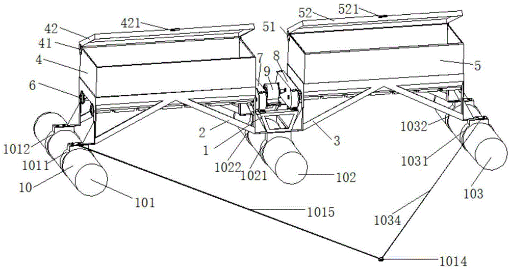
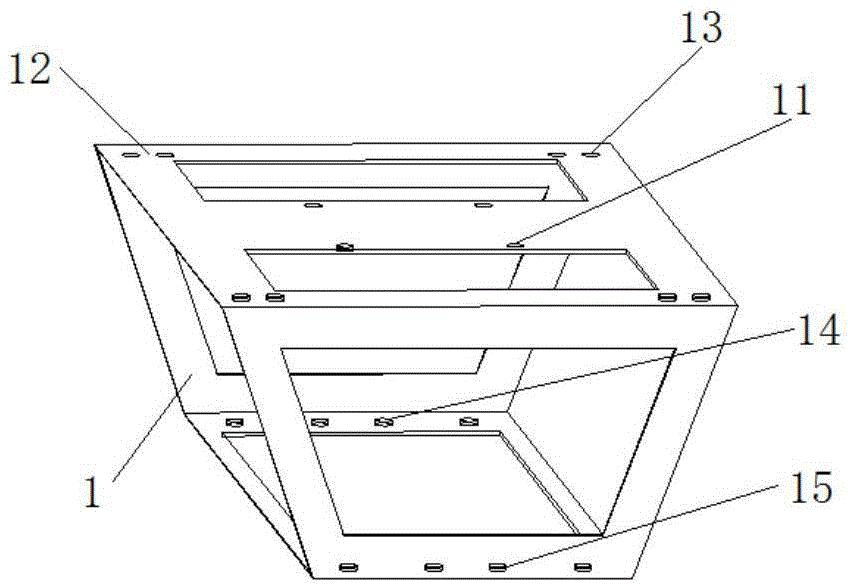
[0026] see figure 1 , figure 2 , image 3 , Figure 4 , Figure 5 , Image 6 , Figure 7 , Figure 8 with Figure 9 , the biaxial multi-port blanking bait feeding machine of the invention comprises a middle frame (1), a left frame (2), a right frame (3), bait boxes (4, 5), a feeding mechanism (6), Single-input and double-output co-steering reducers (7, 8), feeding motors (9), floating bodies (10), and the bait boxes (4, 5) are arranged symmetrically with respect to the middle frame.

[0027] The bait box (4) is connected to the hopper cover (42) through a hinge (41), the hopper cover (42) is provided with a fixed handle (421), and there is a protrusion in the middle of the bottom of the bait box (4). Narrow and long plane (46), the narrow and long plane (46) fits with the flat strip (25) on the...


PUM


Abstract

The invention discloses a two-shaft multi-port discharging feeder which comprises a middle machine frame, a left machine frame, a right machine frame, bait boxes, discharging mechanisms, a discharging motor, floating bodies and a traction rope. The discharging mechanisms are arranged below the bait boxes. The discharging mechanisms are driven by the discharging motor. The bait boxes are supported by the machine frames. The lower ends of the machine frames are provided with the floating bodies. The machine frames are provided with the traction rope. The two-shaft multi-port discharging feeder is characterized in that the two bait boxes are symmetrically installed on the two sides of the middle machine frame, two parallel spiral discharging shafts are arranged below the bait boxes and provided with corresponding feed inlets and discharge outlets, the discharge outlets of the two shafts are evenly distributed and staggered, the two parallel spiral discharging shafts are connected to the two output ends of single-input two-output speed reducers in the same turning direction, and the single-input two-output speed reducers in the same turning direction of the left and right discharging mechanisms are simultaneously driven by the discharging motor in the middle. Bait does not need to be thrown out through a throwing disc, collision impact is reduced, and the bait breakage rate is greatly reduced; the two-shaft multi-port discharging feeder is simple in structure and convenient to maintain, reduces the aquaculture cost and is suitable for shrimp pond aquaculture.

Description

technical field [0001] The invention designs a bait feeding machine for blanking, and in particular relates to a biaxial multi-port blanking bait feeding machine. Background technique [0002] At present, the bait throwing machine placed on the shore is used more often, but the throwing range of this bait throwing machine is relatively small, and the maneuverability is poor. When used in large-scale ponds and reservoirs, a large number of bait feeders need to be placed on the shore. machine to complete the job requirements. In addition, the high-speed rotating bait throwing tray will break the bait, and the broken bait will pollute the water body and affect the breeding efficiency. For some breeding objects that will evenly put bait into the specific esophagus of 2 meters to 3 meters, such as shrimp farming, the existing bait throwing machine can not meet the needs of the work. That is, the existing bait feeding machine has very limited bait feeding methods, poor mobility,...

Claims


Application Information

Patent Timeline
IPC IPC(8): A01K61/02
CPCA01K61/80
Inventor 张丽珍马迪红盛晚霞胡庆松
Owner SHANGHAI OCEAN UNIV
Learn More