Low-radar-section slot array antenna based on holographic surface
A technology of slot array antenna and holographic surface, which is applied in the field of slot array antenna and slot array slot antenna, can solve the problems of high radar cross section and lack of scattering characteristics of the antenna, and achieve the effect of reducing the cross section and improving the scattering characteristics.
- Summary
- Abstract
- Description
- Claims
- Application Information
AI Technical Summary
Problems solved by technology
Method used
Image
Examples
Embodiment 1
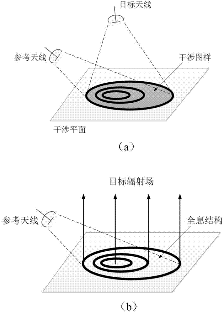
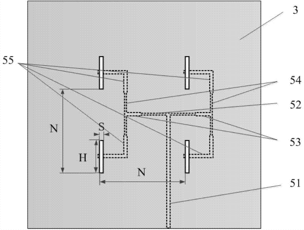
[0030] Reference attached figure 2 The present invention includes a holographic surface 1, a holographic medium plate 2, a radiation floor 3, a radiation medium plate 4, a feeding network 5, a reflective medium plate 6 and a metal medium plate 7; a holographic medium plate 2, a radiation medium plate 4 and a reflective medium plate 6 is a square with a side length of W, and the thicknesses are h1, h2, and h3 respectively, where W=125mm, h1=2mm, h2=1mm, h3=6mm, the radiant dielectric plate 4 and the metal dielectric plate 7 are both dielectric F4B material with a constant of 2.65; the holographic surface 1 is printed on the upper surface of the holographic medium plate 2, the radiation floor 3 and the feed network 5 are printed on the upper and lower surfaces of the radiation medium plate 4, and the metal reflector 7 is printed on On the lower surface of the reflective medium plate 6, the holographic medium plate, the radiation medium plate and the reflective medium plate sequen...
Embodiment 2
[0042] Embodiment 2 has the same structure as embodiment 1, except that the following parameters are adjusted: the width of the gap 15 and the through hole 21 is M1=8.5mm, the length M2=22.5mm, and the side lengths of the four metal patches are n1= 1.6mm, n2=2.8mm, n3=4mm, n4=5.2mm.
Embodiment 3
[0044] Embodiment 3 has the same structure as embodiment 1, except that the following parameters are adjusted: the width of the gap 15 and the through hole 21 is M1=8mm, the length M2=22mm, and the side lengths of the four metal patches are n1=1.2mm. , N2=2.4mm, n3=3.6mm, n4=4.8mm.
[0045] The advantages of the present invention can be further illustrated by the following simulations for the embodiments:
[0046] 1. Simulation content
[0047] 1.1) Use the commercial simulation software HFSS_13.0 to simulate the S parameters of the above-mentioned embodiment 3, and the results are as follows Figure 7 Shown.
[0048] 1.2) Use commercial simulation software HFSS_13.0 to simulate and calculate the far-field radiation pattern of Example 3 above, and the results are as follows Figure 8 As shown, 8(a) is the radiation pattern of the slot array antenna of Embodiment 3 on the x-z plane, and 8(b) is the radiation pattern of the slot array antenna of Embodiment 3 on the y-z plane.
[0049] 1....
PUM
 Abstract
Description
Claims
Application Information
 - R&D
- Intellectual Property
- Life Sciences
- Materials
- Tech Scout
- Unparalleled Data Quality
- Higher Quality Content
- 60% Fewer Hallucinations
Browse by: Latest US Patents, China's latest patents, Technical Efficacy Thesaurus, Application Domain, Technology Topic, Popular Technical Reports.
© 2025 PatSnap. All rights reserved.Legal|Privacy policy|Modern Slavery Act Transparency Statement|Sitemap|About US| Contact US: help@patsnap.com


