
A Method for Realizing Abnormal Detection of Voltage Measurement in DC Protection System

A DC protection system, DC voltage technology, applied in the direction of using digital measurement technology for measurement, can solve the problems of poor reliability, low efficiency, time and energy spent on testing and maintenance, and achieve accurate judgment results and engineering usability. Strong and reliable effect

Active Publication Date: 2018-02-23
EXAMING & EXPERIMENTAL CENT OF ULTRAHIGH VOLTAGE POWER TRANSMISSION COMPANY CHINA SOUTHEN POWER GRID
View PDF4 Cites 0 Cited by
  • Summary
  • Abstract
  • Description
  • Claims
  • Application Information

AI Technical Summary

Problems solved by technology

However, at present, the judgment of the abnormal DC voltage measurement of a single measurement channel can only rely on the observation of the operator, which has low efficiency and poor reliability.
[0003] Specifically, in the DC protection program, the switching of the measurement system will be requested before the protection exit, so as to avoid the protection malfunction caused by the abnormality of a single measurement system; in order to avoid switching to the faulty backup measurement system, the DC If the value exceeds the normal range, it is determined that the backup measurement system is faulty, and the switching of the measurement system is prohibited; in the protection program, the range of the validity check of the measurement value of the backup measurement system is large, and the inspection It can only reflect measurement failures, but not abnormal DC voltage measurement events
For example, in 2015, several voltage measurement abnormalities occurred in a DC power transmission project. A total of 7 measurement voltage divider boards in the measurement system were replaced before returning to normal. The detection and maintenance took a lot of time and energy.

Method used


Image

  • A Method for Realizing Abnormal Detection of Voltage Measurement in DC Protection System

Examples


Embodiment

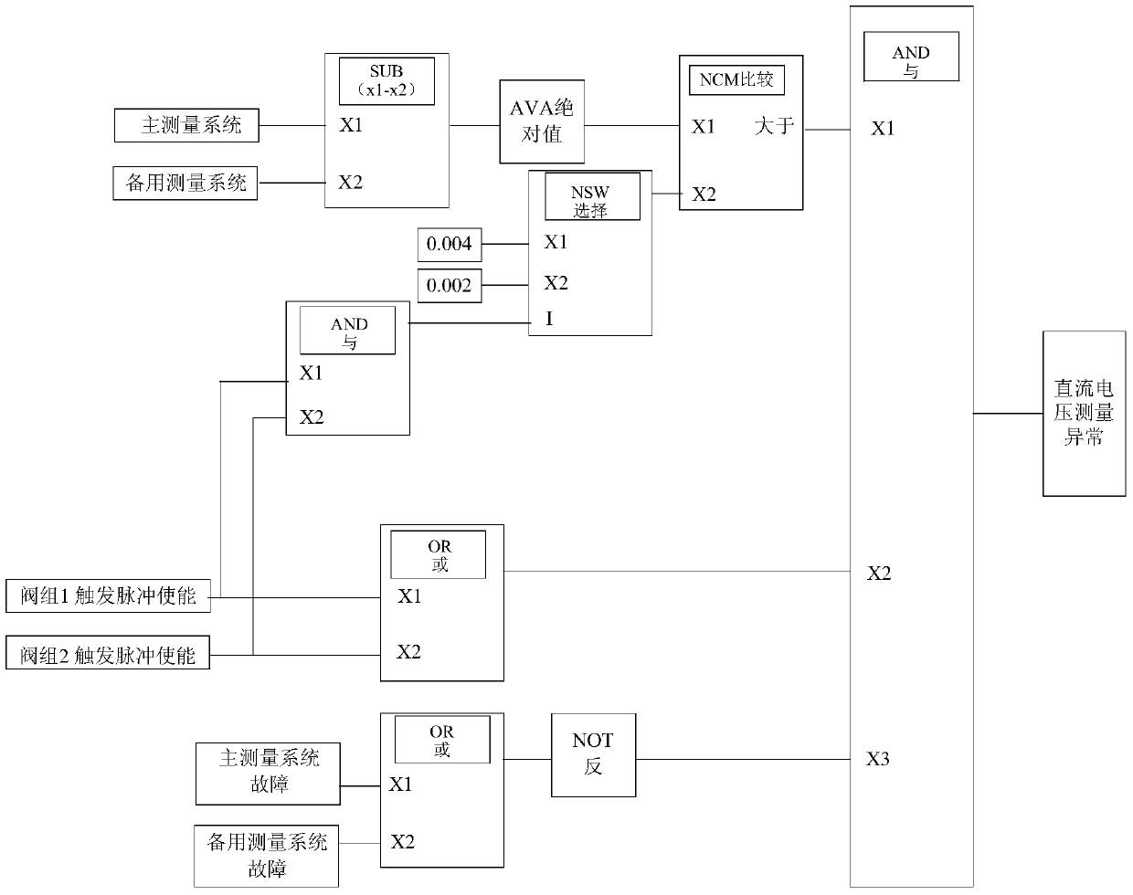
[0022] like figure 1 As shown, a method for detecting abnormal voltage measurement in a DC protection system includes the following steps:

[0023] A. Obtain the absolute value of the difference between the DC voltage UdH of the main measurement system and the standby measurement system in the DC protection system;

[0024] B. At present, the normal error range of the measurement system of a certain project is ±0.002, and the maximum normal error value of the subtraction of the two measured values ​​is 0.004. If the two valve group trigger pulses of one pole in the DC protection system are both in the enabled state, select The corresponding threshold value is 0.004, otherwise the selected threshold value is 0.002;

[0025] C. Comparing the absolute value of the DC voltage UdH difference with the threshold value, and generating a first criterion when the absolute value of the DC voltage UdH difference is higher than the threshold value;

[0026] D. Judging the enabling state ...


PUM


Abstract

The invention provides a method for detecting abnormal voltage measurement in a DC protection system, comprising the following steps: A, obtaining the absolute value of the difference between the DC voltage UdH of the main measurement system and the backup measurement system in the DC protection system; B, Select the corresponding threshold value according to the enabling state of the two valve group trigger pulses of one pole in the DC protection system; C. When the absolute value of the DC voltage UdH difference is higher than the threshold value, the first criterion is generated; D. When any When a valve group trigger pulse is enabled, the second criterion is produced; E, when the two sets of measurement systems are not faulty, the third criterion is formed; F, the first criterion, the second criterion, the third criterion The criterion is used for logical AND operation to obtain the abnormal detection result of DC voltage measurement. The invention can realize the abnormal detection of DC voltage measurement in the DC protection system, can find hidden dangers in time, provides a basis for operators to make decisions, and avoids DC blocking events caused by increased voltage measurement degree.

Description

technical field [0001] The invention relates to the field of high-voltage direct current transmission in electric power systems, in particular to a method for realizing abnormal detection of voltage measurement in a direct current protection system. Background technique [0002] In some UHV DC transmission projects, one pole is formed by connecting two valve groups in series. A single valve group is controlled by the valve group control system, and the valve group protection system can stop the valve group to avoid the expansion of the fault range after the valve group fails; each pole is controlled by the pole control system, and the pole protection system is After a pole fails, the pole can be shut down to avoid the expansion of the fault range. The normal operation of pole control, pole protection, valve group control and valve group protection all depend on the measurement system to transmit the key quantities of the pole and valve group to the above systems. In order ...

Claims


Application Information

Patent Timeline
Patent Type & Authority Patents(China)
IPC IPC(8): G01R19/25
Inventor 邬乾晋陈欢张楠国建宝
Owner EXAMING & EXPERIMENTAL CENT OF ULTRAHIGH VOLTAGE POWER TRANSMISSION COMPANY CHINA SOUTHEN POWER GRID
Learn More