Parallel flow heat exchanger and air conditioner having the same

A parallel flow heat exchanger and heat exchange tube technology, which is applied in evaporator/condenser, lighting and heating equipment, refrigeration components, etc. problems, to achieve the effect of reducing production costs, uniform air temperature, and improving comfort

Inactive Publication Date: 2015-08-19
GD MIDEA AIR-CONDITIONING EQUIP CO LTD +1
View PDF4 Cites 2 Cited by
  • Summary
  • Abstract
  • Description
  • Claims
  • Application Information

AI Technical Summary

Problems solved by technology

[0002] In the single-row parallel-flow heat exchanger in the related art, the refrigerant generally enters from the lower header, and then dissipates heat in multiple heat exchange tubes and then flows out into the upper header. This structure has obvious defects. The temperature difference of the refrigerant will be relatively large, which will lead to a relatively large temperature difference of the outlet air after heat exchange, and the user experience and comfort will be relatively poor; another defect of the bottom-in and top-out structure is that the input and output pipes flow from the parallel flow heat exchanger The parallel flow heat exchanger cannot be installed in the middle, so the left and right heat exchange tubes will have a biased flow, and the input and output tubes on one side will also increase the installation size in the width direction, which is not conducive to saving installation space and increasing cost of production

Method used


Image

  • Parallel flow heat exchanger and air conditioner having the same
  • Parallel flow heat exchanger and air conditioner having the same
  • Parallel flow heat exchanger and air conditioner having the same

Examples


Embodiment Construction

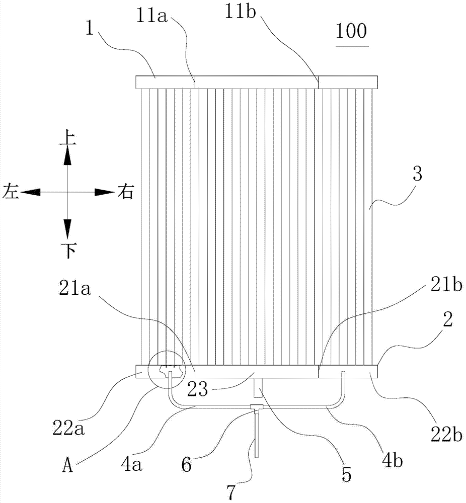
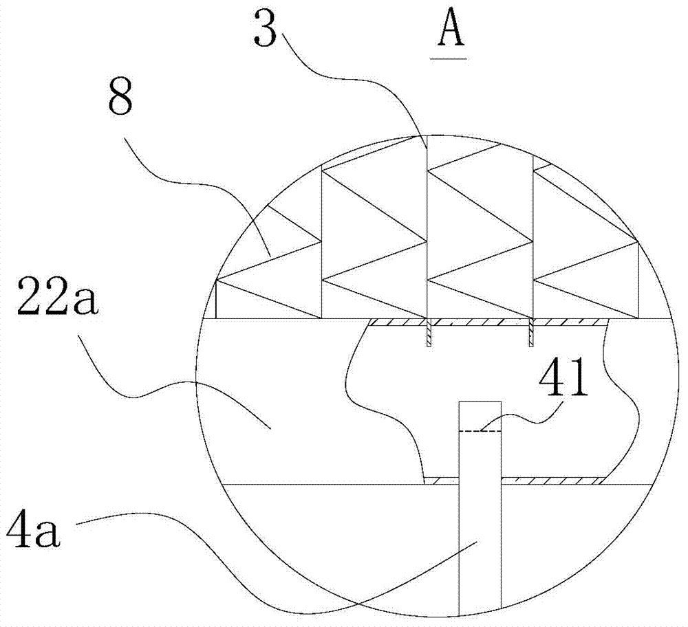
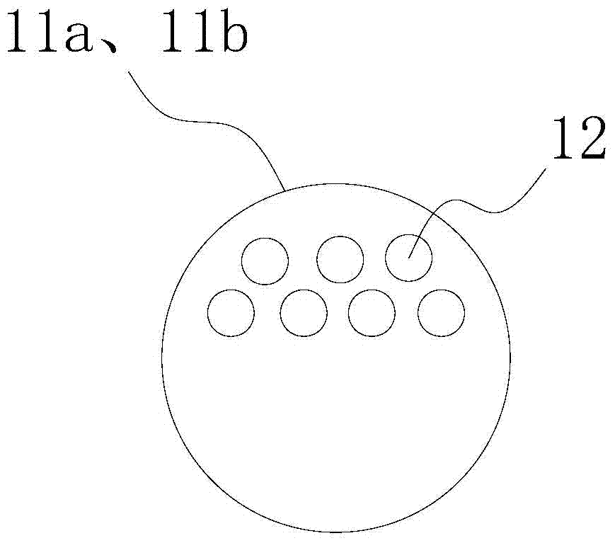
[0030] Embodiments of the invention are described in detail below, examples of which are illustrated in the accompanying drawings. The embodiments described below by referring to the figures are exemplary and are intended to explain the present invention and should not be construed as limiting the present invention.

[0031] In describing the present invention, it should be understood that the terms "center", "longitudinal", "transverse", "length", "width", "thickness", "upper", "lower", "front", " Back", "Left", "Right", "Vertical", "Horizontal", "Top", "Bottom", "Inner", "Outer", "Clockwise", "Counterclockwise", "Axial", The orientation or positional relationship indicated by "radial", "circumferential", etc. is based on the orientation or positional relationship shown in the drawings, and is only for the convenience of describing the present invention and simplifying the description, rather than indicating or implying the referred device or element Must be in a particular ...


PUM


Abstract

The invention discloses a parallel flow heat exchanger and an air conditioner having the same. The parallel flow heat exchanger comprises an upper liquid collecting pipe, a lower liquid collecting pipe, a plurality of heat exchanging pipes, two inlet pipes and an outlet pipe. Two first separation plates that are alternately arranged in the length direction of the upper liquid collecting pipe are arranged inside the upper liquid collecting pipe; and each separation plate is provided with a through hole. Two second separation plates which are alternately arranged are arranged inside the lower liquid collecting pipe for separating the lower liquid collecting pipe into three chambers which are not communicated with each other. The three chambers include inlet chambers on the bilateral sides and an outlet chamber in the middle. In the up-down direction, the two second separation plates are respectively arranged right opposite to the two first separation plates. Each heat exchanging pipe is respectively communicated with the upper liquid collecting pipe and the lower liquid collecting pipe. The two inlet pipes are respectively communicated with the two inlet chambers; and the outlet pipe is communicated with the outlet chamber. The parallel flow heat exchanger according to the embodiment of the invention has the advantages of small temperature difference between the upper outlet air and the lower outlet air, and small space occupation, thereby increasing the comfort level of the user, and effectively reducing the production cost.

Description

technical field [0001] The invention relates to the field of heat exchange, in particular to a parallel flow heat exchanger and an air conditioner with the parallel flow heat exchanger. Background technique [0002] In the single-row parallel-flow heat exchanger in the related art, the refrigerant generally enters from the lower header, and then dissipates heat in multiple heat exchange tubes and then flows out into the upper header. This structure has obvious defects. The temperature difference of the refrigerant will be relatively large, which will lead to a relatively large temperature difference of the outlet air after heat exchange, and the user experience and comfort will be relatively poor; another defect of the bottom-in and top-out structure is that the input and output pipes flow from the parallel flow heat exchanger The parallel flow heat exchanger cannot be installed in the middle, so the left and right heat exchange tubes will have a biased flow, and the input a...

Claims


Application Information

Patent Timeline
Patent Type & Authority Applications(China)
IPC IPC(8): F25B39/00
CPCF25B39/00F25B2339/00
Inventor 吴君
Owner GD MIDEA AIR-CONDITIONING EQUIP CO LTD
Why Eureka
Try Eureka