Direct expansion heat recovery energy saving method and device
A direct expansion heat recovery and energy-saving device technology, applied in the field of air conditioning, can solve the problems of large size and complex system, and achieve the effect of simple structure
- Summary
- Abstract
- Description
- Claims
- Application Information
AI Technical Summary
Problems solved by technology
Method used
Image

Examples
Embodiment 1
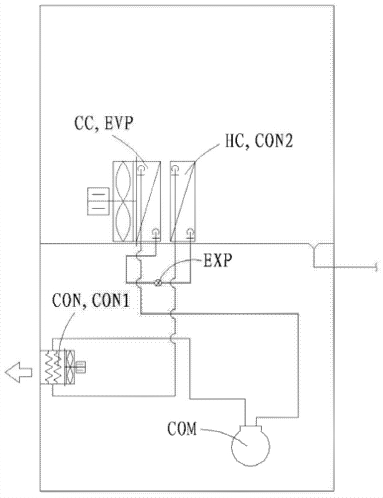
[0104] Such as image 3 As shown, it can be seen that this embodiment is mainly composed of a compressor COM, a condenser CON, an expansion valve EXP (expansion valve EXPANSION VALVE) and an evaporator EVP to form a complete refrigeration cycle, wherein: the condenser CON is composed of the first condenser CON1 and the second condenser CON2 are connected in series. Controlling the heat dissipation required by the second condenser CON2 is a proportional control of the heat dissipation of the first condenser CON1 to achieve precise control of the heat dissipation required by the second condenser CON2. The second condenser CON2 is used for heat recovery heater, and will not affect the normal operation of the compressor COM. That is to say, only need to start the compressor, through heat recovery, it can have the functions of cooling, dehumidification and heating at the same time. It is suitable for industries requiring low humidity and constant temperature (lower temperature) s...
Embodiment 2
[0106] Such as Figure 4 As shown, the evaporator EVP in this embodiment is composed of the first evaporator EVP1 and the second evaporator EVP2 connected in series. In this embodiment, controlling the heat dissipation required by the second condenser CON2 is a proportional control of the heat dissipation of the first condenser CON1, so as to accurately control the heat dissipation required by the second condenser CON2, and the second condenser CON2 is used as The heat recovery heater will not affect the normal operation of the compressor. The heat absorption required by the second evaporator EVP2 is proportional to the heat absorption of the first evaporator EVP1, so as to accurately control the heat absorption of the second evaporator EVP2. The second evaporator EVP2 is used for cooling and dehumidification. When its capacity is lower than that of the heat recovery heater, the system will have a high temperature heating effect without affecting the normal operation of the co...
Embodiment 3
[0108] Such as Figure 5 As shown, another embodiment of the present invention includes the third condenser CON3 and the fourth condenser CON4 connected in series, the third condenser CON3 and the fourth condenser CON4 connected in series and the first condenser CON2 connected in series It is connected in parallel with the two series circuits of the second condenser CON2, and a solenoid valve S (solenoid valve SOLENOID VALVE) is used to control and start the heat recovery heating or heat recovery humidification function. That is to say, it only needs to start the compressor, and through heat recovery, it can have the functions of cooling, dehumidification, heating, and humidification at the same time. It is suitable for industries that require constant temperature and humidity, such as computer rooms, constant temperature and humidity machines in the electronics industry, and drying processes for dewaxing casting shell molds.
[0109] In this embodiment, the above-mentioned f...
PUM
 Abstract
Description
Claims
Application Information
 - R&D
- Intellectual Property
- Life Sciences
- Materials
- Tech Scout
- Unparalleled Data Quality
- Higher Quality Content
- 60% Fewer Hallucinations
Browse by: Latest US Patents, China's latest patents, Technical Efficacy Thesaurus, Application Domain, Technology Topic, Popular Technical Reports.
© 2025 PatSnap. All rights reserved.Legal|Privacy policy|Modern Slavery Act Transparency Statement|Sitemap|About US| Contact US: help@patsnap.com