A grinding wheel type regulating valve

A regulating valve and grinding wheel technology, applied in the field of regulating valves, can solve the problems of affecting the working environment, high noise, single structure of internal parts, etc., and achieve the effect of small size and reasonable structure

Active Publication Date: 2017-06-13
ZHEJIANG JINGHUA MEASUREMENT & CONTROL EQUIP
View PDF1 Cites 0 Cited by
  • Summary
  • Abstract
  • Description
  • Claims
  • Application Information

AI Technical Summary

Problems solved by technology

[0003] There are certain defects in the production process of the grinding wheel control valve. Since the contact sealing surface between the upper grinding wheel and the lower grinding wheel is always in a dynamic sealing state, and the sealing effect of the two is mainly affected by the following factors: 1. The upper grinding wheel is on the lower grinding wheel. 2. The size of the contact sealing surface between the upper grinding wheel and the lower grinding wheel, 3. The wear degree of the contact sealing surface; due to the frequent friction of the upper and lower grinding wheel contact surfaces of the existing grinding wheel control valve, it is easy to And wear occurs, and at this time, the pressing force of the upper grinding wheel on the lower grinding wheel will decrease, and water leakage will occur when contacting the sealing surface, which will affect the control of the water injection in the oil field, and also increase the valve switching torque and increase the output power of the motor. It causes waste of power resources and directly affects the service life of intelligent flow controllers and grinding wheel control valves
At the same time, under the condition of high pressure, the valve stem of the grinding wheel regulating valve will fail due to wear and tear of the valve stem seal.
[0004] In addition, due to the relatively simple structure of the internal parts of the current control valve, in the working condition of high pressure difference, due to the relatively large pressure difference of the medium, the phenomenon of flashing and cavitation will occur when the valve flow rate is too fast, resulting in loud noise when the valve is working , affecting the working environment
At the same time, due to the occurrence of flash cavitation phenomenon, the fluid will severely wash the valve trim and cause cavitation damage to the valve.

Method used


Image

  • A grinding wheel type regulating valve
  • A grinding wheel type regulating valve
  • A grinding wheel type regulating valve

Examples


Embodiment Construction

[0024] The specific embodiments of the present invention will be described in further detail below in conjunction with the drawings and embodiments. The following examples are used to illustrate the present invention, but not to limit the scope of the present invention.

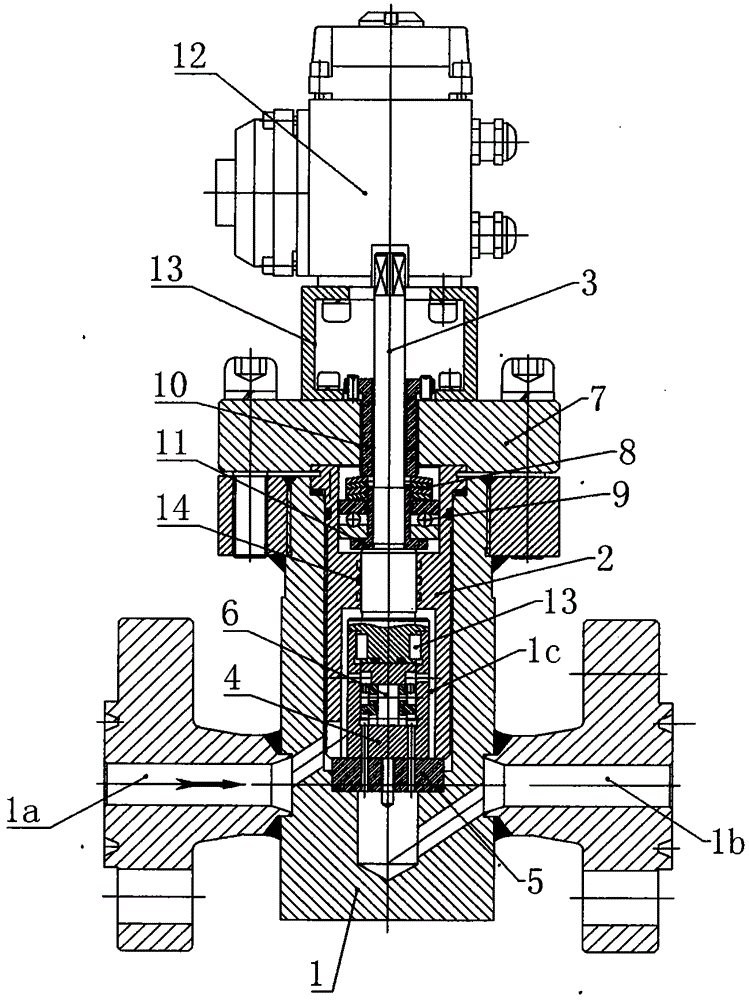
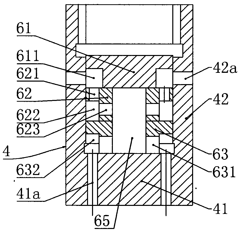
[0025] Combine Figure 1 to Figure 6 As shown, this embodiment discloses a grinding wheel type regulating valve, including a valve body 1, a valve cover 2, and a valve stem 3. The valve body 1 is provided with a valve cylinder 1c, and both sides of the valve body 1 are respectively connected to the valve cylinder The liquid inlet 1a and the liquid outlet 1b of 1c, the valve stem 3 seals through the valve cover 2 and is vertically inserted in the valve cylinder 1c. The valve stem 3 and the valve cover 2 are fitted with multiple O-rings, The valve cylinder 1c is provided with a grinding wheel adjustment assembly. The grinding wheel adjustment assembly includes a movable grinding cylinder 4 fixedly connected to th...


PUM


Abstract

The invention provides a grinding wheel type adjusting valve which comprises a valve body, a valve cover and a valve rod. A valve cylinder is arranged in the valve body, the valve rod penetrates through the valve cover in a sealing mode and is vertically inserted in the valve cylinder, and a grinding wheel adjusting assembly is arranged in the valve cylinder. The grinding wheel adjusting assembly comprises a movable grinding cylinder fixedly connected to the valve rod, and a static valve seat fixed in the valve cylinder. The movable grinding cylinder and the static valve seat are arranged in an up-and-down-face contact mode and are in dynamic seal fit, and the valve rod is further provided with a pressure maintaining assembly enabling the movable grinding cylinder to be elastically attached to the static valve seat. The movable grinding cylinder and the static valve seat are provided with through hole structures respectively. The movable grinding cylinder comprises a movable grinding wheel matched with the static valve seat in a face contact mode and a throttling grinding cylinder of a cylindrical structure, the top of the throttling grinding cylinder is connected to the lower end of the valve rod, and a throttling assembly used for multi-level pressure reducing is arranged in the throttling grinding cylinder. A driving unit for driving the valve rod to rotate in the circumferential direction is arranged at the upper end of the valve rod. The grinding wheel type adjusting valve can conduct multi-level throttling and pressure reducing so as to adapt to the use environment with the high pressure difference, the abrasion caused by the sealing failure can be automatically offset, and the leakage amount of the adjusting valve is reduced.

Description

Technical field [0001] The invention relates to a regulating valve, in particular to a grinding wheel type regulating valve. Background technique [0002] At present, water flooding and oil flooding in oil fields mainly use regulating valves to control water injection flow. For example, a grinding wheel type regulating valve: the grinding wheel type regulating valve is formed with a fluid medium inlet on one side and a fluid medium outlet on the other side. A lower grinding wheel and an upper grinding wheel are arranged inside the valve cavity of the valve body. The lower grinding wheel and the upper grinding wheel are symmetrically formed with orifices connecting the fluid medium inlet and the fluid medium outlet. The two grinding wheels rotate symmetrically, and the flow is adjusted by changing the flow cross-sectional area of ​​the two grinding wheels. . [0003] The grinding wheel control valve has certain defects in the production process. Because the contact sealing surfac...

Claims


Application Information

Patent Timeline
Patent Type & Authority Patents(China)
IPC IPC(8): F16K3/08F16K3/10F16K3/30F16K27/08F16K47/04F16K47/08
CPCF16K3/08F16K3/10F16K3/30F16K27/08F16K47/045F16K47/08
Inventor 戴国胜马洛辰陈景划
Owner ZHEJIANG JINGHUA MEASUREMENT & CONTROL EQUIP
Why Eureka
Try Eureka