Cooling system, control method applying cooling system and vehicle

A heat dissipation system and control method technology, applied in the field of vehicles, can solve the problems of increasing the water resistance of the heat dissipation circuit, increasing power consumption, and limited improvement range, and achieve the effects of improving the degree of automatic control, reducing fuel consumption, and reducing power loss

Inactive Publication Date: 2015-08-19
BEIQI FOTON MOTOR CO LTD
View PDF8 Cites 11 Cited by
  • Summary
  • Abstract
  • Description
  • Claims
  • Application Information

AI Technical Summary

Problems solved by technology

[0003] However, there are also some problems in the use of the hydraulic retarder. The main manifestations are: the heat dissipation system of the hydraulic retarder is shared with the engine heat dissipation system, and the heat dissipation demand during braking is often greater than that of the engine when it is working. The heat dissipation system designed for engine heat dissipation has the defect of insufficient heat dissipation capacity. Although the heat dissipation capacity can be increased by appropriately increasing the radiator and engine water pump, the improvement is limited
At the same time, since the heat dissipation pipeline of the hydraulic retarder is connected in series with the original engine heat dissipation circuit, when the engine is working normally, the heat dissipation pipeline of the hydraulic retarder will increase the water resistance of the heat dissipation circuit, thereby increasing power consumption and increasing Increased engine fuel consumption

Method used


Image

  • Cooling system, control method applying cooling system and vehicle
  • Cooling system, control method applying cooling system and vehicle
  • Cooling system, control method applying cooling system and vehicle

Examples


Embodiment Construction

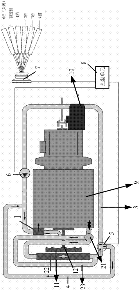
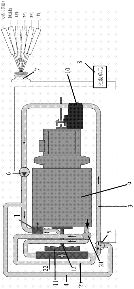
[0030] Specific embodiments of the present invention will be described in detail below in conjunction with the accompanying drawings. It should be understood that the specific embodiments described here are only used to illustrate and explain the present invention, and are not intended to limit the present invention.

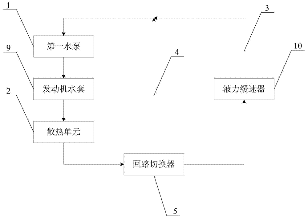
[0031] Such as figure 1 As shown, the heat dissipation system of the present invention communicates with the engine water jacket 9 and the hydraulic retarder 10 respectively, and is used to dissipate heat for the engine or the hydraulic retarder 10 . Wherein, the heat dissipation system of the present invention includes a heat dissipation unit 2, which communicates with the engine water jacket 9, and is used to dissipate heat to the coolant flowing through the engine water jacket 9; a first return pipeline 3, which communicates with the heat dissipation unit 2 and the engine water jacket respectively. sleeve 9, and the first return line 3 is also connected to t...


PUM


Abstract

The invention discloses a cooling system, a control method and a vehicle. The cooling system comprises a cooling unit (2) communicated with an engine water jacket (9) for cooling a coolant flowing through the engine water jacket, a first reflow pipeline (3) respectively communicated with the cooling unit and the engine water jacket and communicated with a hydraulic retarder (10) for enabling the coolant flowing out from the cooling unit to absorb the heat of the hydraulic retarder and to cool and reflow, a second reflow pipeline (4) respectively communicated with the cooling unit and the engine water jacket for cooling and reflowing the coolant flowing out from the cooling unit, and a loop switcher (5) arranged between the cooling unit and the first reflow pipeline and the second reflow pipeline for controlling the conduction and the cutoff of the first reflow pipeline and the second reflow pipeline. The cooling system can separate the hydraulic retarder from a cooling pipeline of an engine to reduce the fuel consumption of the engine.

Description

technical field [0001] The invention relates to a heat dissipation system, in particular to a heat dissipation system suitable for an engine and a hydraulic retarder, a control method using the heat dissipation system and a vehicle. Background technique [0002] As a means of auxiliary braking, the application of hydraulic retarder on heavy commercial vehicles is gradually increasing. Vehicles equipped with hydraulic retarders can greatly reduce the use of service brakes when going down long slopes, and ensure that the service brakes are always in good condition, thereby ensuring driving safety. [0003] However, there are also some problems in the use of the hydraulic retarder. The main manifestations are: the heat dissipation system of the hydraulic retarder is shared with the engine heat dissipation system, and the heat dissipation demand during braking is often greater than that of the engine when it is working. The heat dissipation system designed for engine heat dissi...

Claims


Application Information

Patent Timeline
Patent Type & Authority Applications(China)
IPC IPC(8): B60K11/04
Inventor 黄建国刘知汉梁立东曲友辉
Owner BEIQI FOTON MOTOR CO LTD
Why Eureka
Try Eureka