Pneumatic assisted chemical raw material mixing tank

A technology of chemical raw materials and mixing tanks, applied in mixers, chemical instruments and methods, chemical/physical processes, etc., can solve problems such as thin substances, large sediments, low viscosity and concentration, and achieve better effects, Good mixing effect, avoiding the effect of uneven viscosity

Inactive Publication Date: 2015-08-19
王英英
View PDF6 Cites 4 Cited by
  • Summary
  • Abstract
  • Description
  • Claims
  • Application Information

AI Technical Summary

Problems solved by technology

[0002] The mixing tank currently used for mixing chemical raw materials adopts a straight-up mixing method. Due to the straight-up mixing method, the disadvantage of this mixing method is that it is prone to uneven mixing in the mixing tank after the mixing is completed. , it is easy to appear upper, middle and lower layers in the tank. The upper layer is thin, with low viscosity and concentration, while the lower layer has more sediment and higher concentration.
Even after a long time of stirring, the viscous substance at the bottom is difficult to mix evenly with the thin liquid on the upper layer, and the purpose of sufficient mixing cannot be achieved, and the mixed liquid flowing out from the bottom outlet is not uniform

Method used


Image

  • Pneumatic assisted chemical raw material mixing tank
  • Pneumatic assisted chemical raw material mixing tank
  • Pneumatic assisted chemical raw material mixing tank

Examples


Embodiment Construction

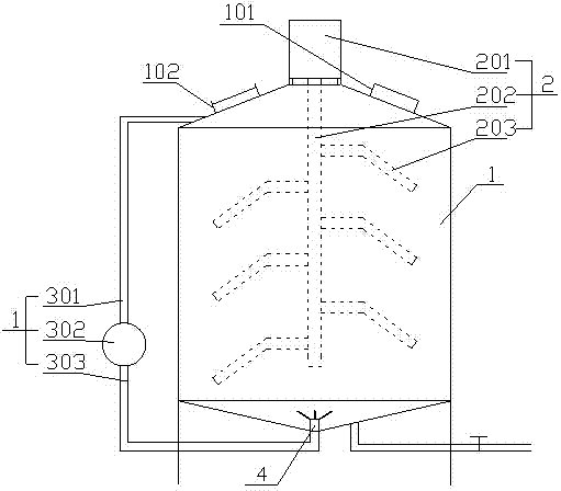
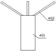
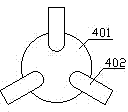
[0020] refer to Figure 1-4 , a pneumatically assisted chemical raw material mixing tank, comprising a tank body (1), a stirring system (2), a pneumatically assisted device 3 and a gas distributor 4;

[0021] The top of the tank body 1 is in the shape of a circular platform, with a through hole in the middle of the circular platform, and a feeding port 101 and an air outlet opening on the side wall of the circular platform. A discharge port is provided on the side wall, and an observation port 102 is provided on the side wall of the round platform at the top of the tank body 1, and the observation port 102 is closed by transparent glass.

[0022] The stirring system is located at the top of the tank body 1. The stirring system includes a motor 201, a stirring shaft 202 and a stirring blade 203. The motor 201 of the stirring system is installed on the top of the tank body 1. One end of the stirring shaft 202 is connected to the rotating shaft of the motor, and the other end...


PUM


Abstract

The invention provides a pneumatic assisted chemical raw material mixing tank. The mixing tank comprises a tank body, a stirring system and a pneumatic assisting device, wherein the top of the tank body is in the shape of a circular table; a through hole is formed in a middle position of the circular table; the bottom of the tank body is in the shape of an inverted circular table; an air intake opening is formed in the middle position of the inverted circular table; the stirring system comprises a motor, a stirring rotating shaft and stirring blades; a motor of the stirring system is arranged at the top end of the tank body; one end of the stirring rotating shaft is connected with a rotating shaft of the motor, and the other end of the stirring rotating shaft extends into the tank body; the stirring blades are connected to the stirring rotating shaft; the pneumatic assisting device comprises an air intake pipe, a vacuum pump and an air outlet pipe; a first end of the air intake pipe is connected to the stirring rotating shaft; a first end of the air outlet pipe is connected with an air outlet of the vacuum pump; a second end of the air outlet pipe is connected with an air inlet opening in the bottom of the tank body. By using the optimally designed mixing tank, a chemical raw material in the mixing tank can be more uniformly mixed, non-uniform vertical viscosity of the mixed chemical raw material in the mixing tank is avoided, and the mixing effect is better.

Description

technical field [0001] The invention relates to the technical field of chemical production machinery and equipment, in particular to a gas-assisted chemical raw material mixing tank. Background technique [0002] The mixing tank currently used for mixing chemical raw materials adopts a straight-up mixing method. Due to the straight-up mixing method, the disadvantage of this mixing method is that it is prone to uneven mixing in the mixing tank after the mixing is completed. , it is easy to appear upper, middle and lower layers in the tank. The upper layer is thin, with low viscosity and concentration, while the lower layer has more sediment and higher concentration. Even after a long time of stirring, the viscous substance at the bottom is difficult to mix evenly with the thin liquid on the upper layer, and the purpose of sufficient mixing cannot be achieved, and the mixed liquid flowing out from the bottom outlet is not uniform. Contents of the invention [0003] With reg...

Claims


Application Information

Patent Timeline
IPC IPC(8): B01F13/02B01F13/10B01F15/02B01F33/40
Inventor 王英英
Owner 王英英
Why Eureka
Try Eureka