An integrated honeycomb flue gas denitrification catalyst structure

A denitrification catalyst and honeycomb technology, which is applied in the field of integrated honeycomb flue gas denitrification catalyst structure, can solve the problems of catalyst reaction efficiency decline, catalyst installation and replacement difficulty, and poor controllability of the operation process, so as to improve installation, replacement and flexible use The effect of improving the stability and continuity of use, reducing the cost of use and maintenance

Inactive Publication Date: 2018-01-19
SUZHOU HUALE AIR POLLUTION CONTROL TECH EXPAND CO LTD
View PDF6 Cites 0 Cited by
  • Summary
  • Abstract
  • Description
  • Claims
  • Application Information

AI Technical Summary

Problems solved by technology

[0002] At present, in many industries such as coal-fired power generation and coal-fired boilers, because the tail gas after fuel combustion contains a large amount of polluting gases such as nitrogen oxides, sulfides, and carbon dioxide, it causes serious pollution to the air environment and is the formation of The main source of acid rain, so the current treatment of burn-up flue gas is an important part of ensuring the atmospheric environment. At present, in the process of flue gas treatment, the main method is SCR flue gas denitrification, and in this denitrification method, mainly rely on A chemical reaction is carried out between the catalyst and the flue gas to achieve the purpose of treatment. In order to meet the needs of use, the honeycomb catalyst structure is currently used for flue gas treatment. However, it is found in use that the structure of the currently used honeycomb catalyst is relatively fixed, and The controllability of the operation process is poor. On the one hand, it is difficult to install and replace the catalyst, and when a partial failure occurs, the catalyst structure needs to be replaced as a whole. The resource utilization rate is low, and the operation reliability and continuity are poor. On the other hand, it is very easy Due to the high temperature generated by the flue gas, the reaction efficiency of the catalyst is reduced, or the structure of the catalyst is blocked due to the deposition of dust in the flue gas, which seriously affects the quality of the flue gas and the service life of the catalyst. Therefore, in view of this situation, it is urgent to develop a An inventive flue gas denitrification catalyst structure to overcome the current deficiencies and meet the needs of practical use

Method used


Image

  • An integrated honeycomb flue gas denitrification catalyst structure

Examples


Embodiment Construction

[0011] In order to make the technical means, creative features, objectives and effects of the present invention easy to understand, the present invention will be further explained below in conjunction with specific embodiments.

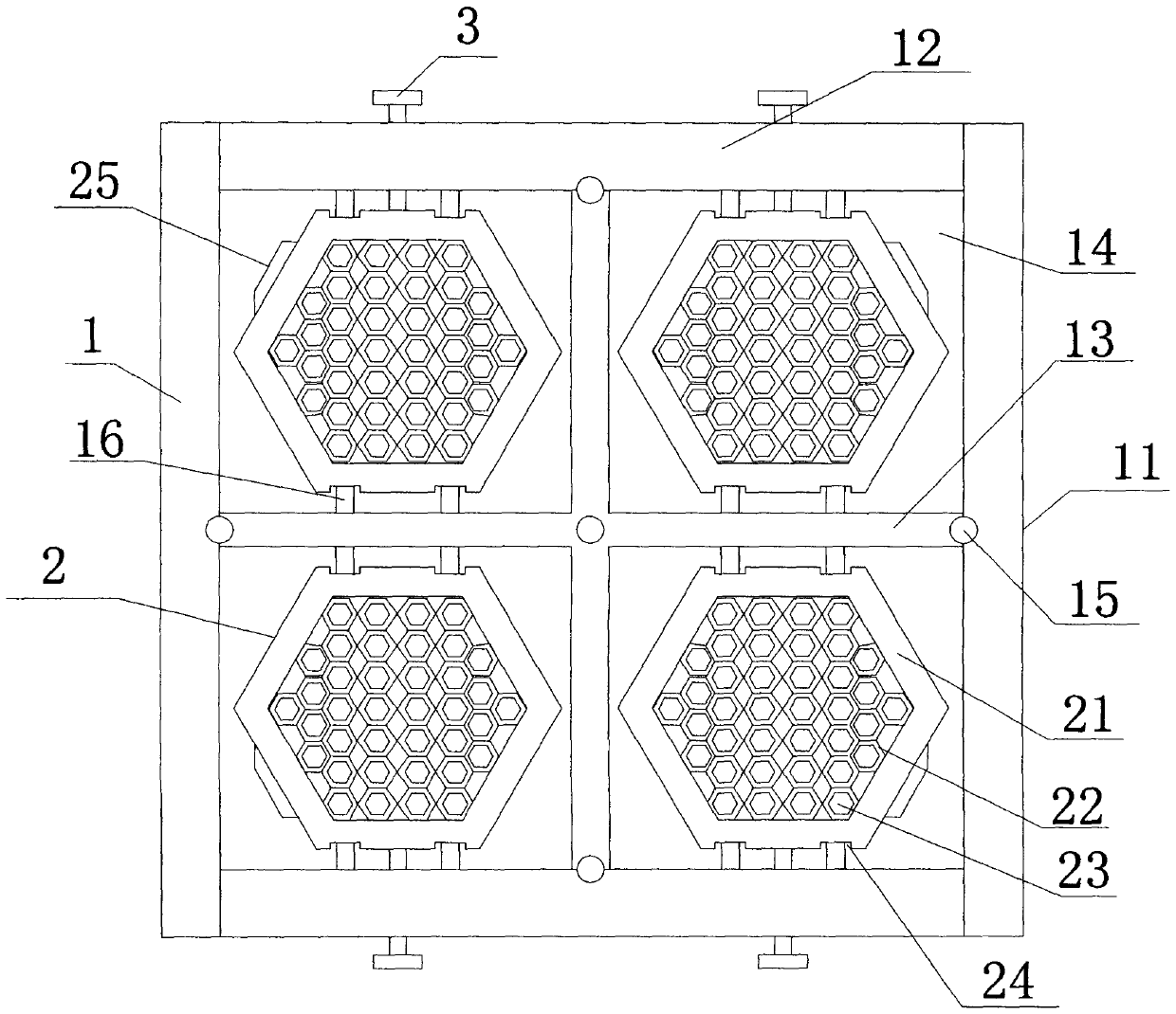
[0012] Such as figure 1 The integrated honeycomb type flue gas denitration catalyst structure includes a positioning frame 1 and a catalyst frame 2, wherein the positioning frame 1 includes a column 11, a beam 12, and a partition 13, and the column 11 and the beam 12 are connected and connected first in sequence. To form the working chamber 14 of the rectangular space frame structure, at least two partitions 13 are distributed in a "cross" shape, and the working chambers 14 are equally divided. The intersections of the partitions 13 and the intersections of the partitions 13 and the columns 11 and the beams 12 There are also circulating cooling pipes 15 at the positions, and at least four positioning pulleys 16 are evenly distributed on the surface of th...


PUM


Abstract

The invention relates to an integrated honeycomb flue gas denitrification catalyst structure, which includes a positioning frame and a catalyst skeleton, wherein the positioning frame includes a column, a beam and a partition, and the column and the beam are first connected in sequence to form a working chamber of a rectangular space frame structure , there are at least two partitions, and they are distributed in a "ten" shape. The catalyst frame is a regular hexagonal prism structure, which is embedded in the positioning frame through the positioning pulley and is against the partition. The catalyst frame includes a protective wall and a drainage plate, and the drainage plate is embedded in the Inside the protective wall, a number of regular hexagonal diversion holes arranged in an array are formed, connecting grooves are provided on the outer surface of the protective wall, and at least one ultrasonic vibration device is additionally provided on the outer surface of the protective wall of the catalyst skeleton. The invention adopts an embedded assembly structure, thereby greatly improving the flexibility of equipment installation and replacement and use, reducing the cost of use and maintenance, and at the same time, it can also perform effective temperature adjustment and dust anti-deposition treatment during use.

Description

Technical field [0001] The invention relates to an integrated honeycomb type flue gas denitration catalyst structure, belonging to the technical field of flue gas denitration purification treatment equipment. Background technique [0002] At present, in many industries such as coal-fired power generation and coal-fired boilers, the exhaust gas after fuel combustion contains a large amount of polluting gases such as nitrogen oxides, sulfides, carbon dioxide, etc., which causes serious pollution to the air environment and forms The main source of acid rain, so the current burn-up flue gas treatment is an important part of ensuring the atmospheric environment. At present, in the flue gas treatment process, the main method is SCR flue gas denitrification, and the denitrification method mainly depends on The chemical reaction between the catalyst and the flue gas is to achieve the purpose of treatment. In order to meet the needs of use, currently the honeycomb catalyst structure is ma...

Claims


Application Information

Patent Timeline
Patent Type & Authority Patents(China)
IPC IPC(8): B01D53/88B01D53/56
Inventor 俞旸殷昊东
Owner SUZHOU HUALE AIR POLLUTION CONTROL TECH EXPAND CO LTD
Why Eureka
Try Eureka