
Multipath light modulation apparatus

A multi-channel dimming and one-channel technology is applied in the direction of lighting devices, lamp circuit layout, light sources, etc., which can solve the problems of large PCB board area and high circuit cost, and achieve the effect of improving the freedom of choice and promoting application

Active Publication Date: 2015-08-12
金红涛
View PDF11 Cites 13 Cited by
  • Summary
  • Abstract
  • Description
  • Claims
  • Application Information

AI Technical Summary

Problems solved by technology

The cost of the control part of the circuit is high and occupies a large area of ​​the PCB board

Method used


Image

  • Multipath light modulation apparatus
  • Multipath light modulation apparatus
  • Multipath light modulation apparatus

Examples


Embodiment Construction

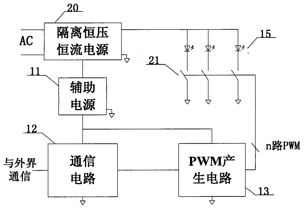
[0030] refer to Figure 4 , Figure 4 The structure of a non-isolated constant voltage constant current multi-channel dimming circuit according to an embodiment of the present invention is shown. In this embodiment, the single-chip integrated processor and its auxiliary circuit 42 complete the communication function and the multi-channel PWM signal output function, and no additional single-chip microcomputer is needed to generate multiple PWM signals. Also, a non-isolated power supply 40 is used instead of the isolated power supply 20 . Usually, monolithic integrated processor supply voltage V CC It is 3.3V, and the high level of the output PWM is 3.3V; the current source and sink capacity of the GPIO pin is above 10mA. When NMOS is selected as the current switch, if the NMOS Miller platform gate-source voltage V GS If it is less than 3.3V, the PWM signal can switch NMOS normally; if the NMOS Miller platform gate-source voltage V GS If it is greater than 3.3V, you need to...


PUM


Abstract

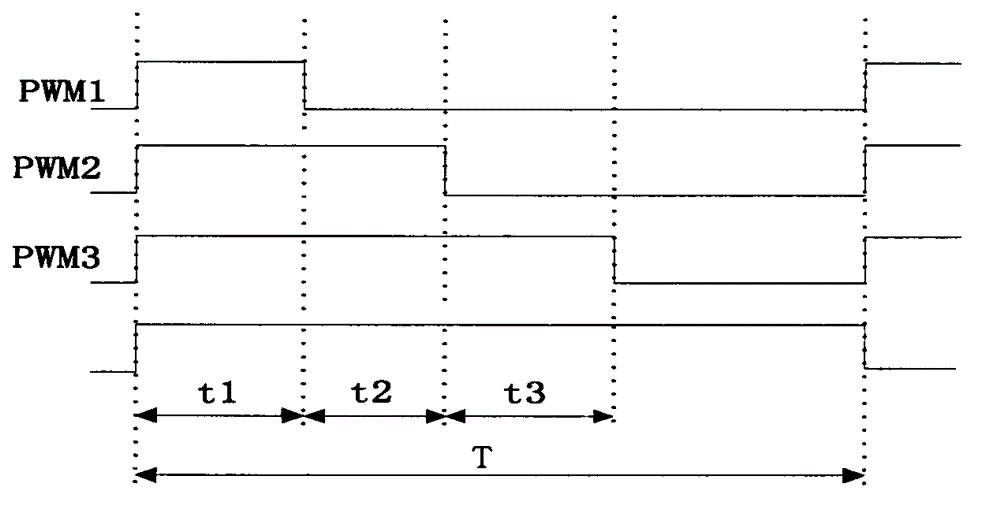
The invention discloses a multipath light modulation apparatus. The multipath light modulation apparatus comprises a power supply circuit, a single-chip integrated communication processor and circuit, and multipath adjustable current circuits. AC power is input to the power supply circuit, an output first-path DC power supply supplies power to multipath LED loads, an output second-path DC power supply supplies power to the single-chip integrated communication processor and circuit, and the anode of the output first-path DC power supply is connected with the anodes of the multipath LED loads; a single-chip integrated communication processor integrates a communication function and a multipath PWM signal output function into one chip, and the single-chip integrated communication processor and circuit communicates with the outside to obtain an instruction and outputs multipath PWM signals according to the instruction; and each path of the multipath adjustable current circuits is connected in series between the cathode of each LED load and ground potential and is respectively controlled by one PWM signal, and under the control of the PWM signals, the size of the current of the LED loads is changed. According to the invention, the multipath light modulation apparatus improves the circuit integration of a control portion and the selection freedom of an AC / DC power supply, and reduces the cost of the multipath light modulation apparatus.

Description

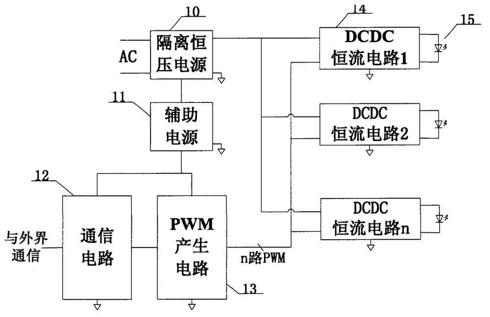
technical field [0001] The present invention relates to a multi-channel dimming device, in particular, relates to a device for driving multiple light-emitting diode (LED) loads, individually adjusting the load current of each LED, and controlling brightness, color temperature or color, and comprising the multiple Lighting device for road dimming device. Background technique [0002] As a new generation of lighting sources, LED lamp beads can emit light with different color temperatures and colors, making multi-channel LED color lighting gradually widely used. Currently on the market, there are two ways to drive multiple LED loads. The first approach is a two-level structure, such as figure 1 shown. The first stage realizes AC / DC constant voltage, and the second stage uses multiple PWM controllable DC / DC to realize constant current. The two output windings of the first stage isolation transformer supply power to the second stage and the control part respectively. The con...

Claims


Application Information

Patent Timeline
Patent Type & Authority Applications(China)
IPC IPC(8): H05B37/02
Inventor 金红涛程振东金红平
Owner 金红涛
Learn More