Color filter substrate and liquid crystal panel
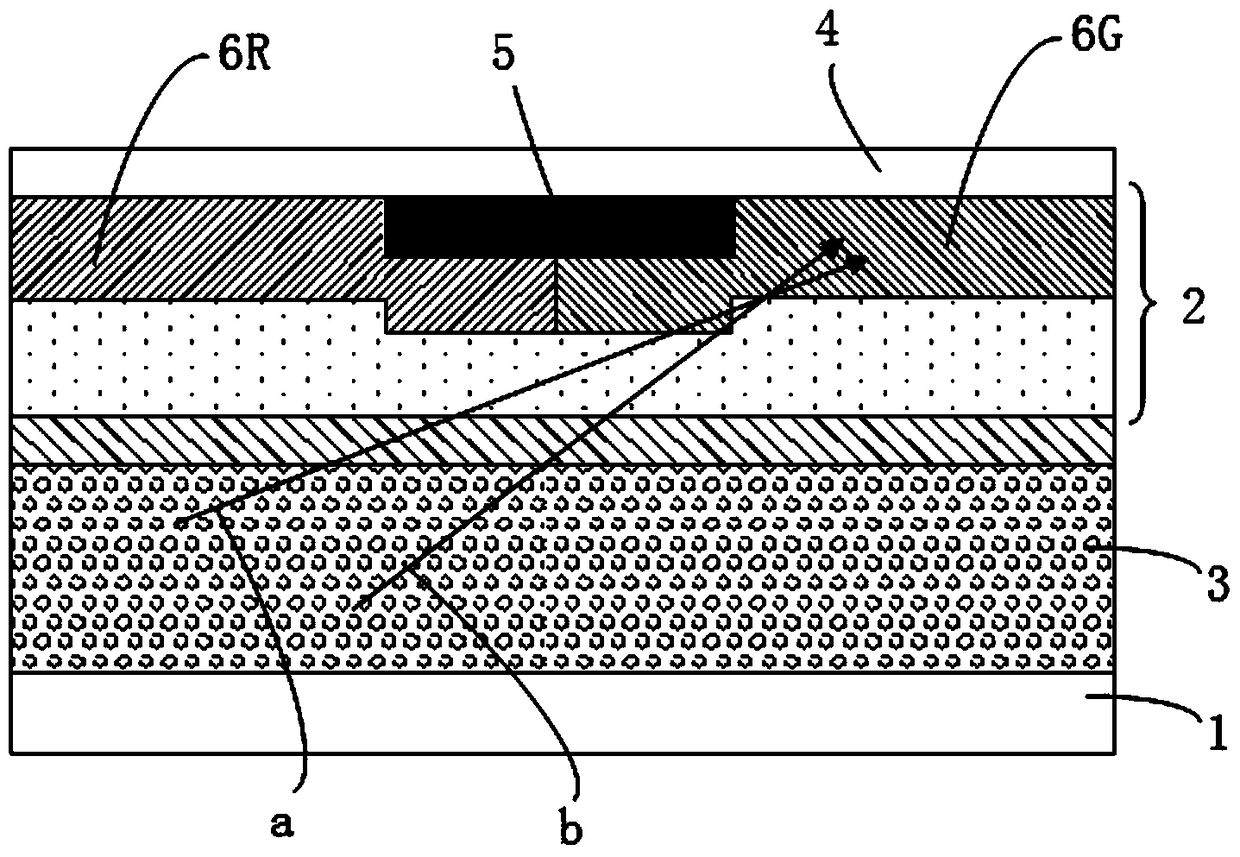
A color filter substrate and liquid crystal layer technology, applied in optics, nonlinear optics, instruments, etc., can solve the problems of increasing the optical anisotropy of liquid crystals and the difficulty of developing new liquid crystal materials, so as to improve the role of large vision Partial effect
- Summary
- Abstract
- Description
- Claims
- Application Information
AI Technical Summary
Problems solved by technology
Method used
Image
Examples
Embodiment 1
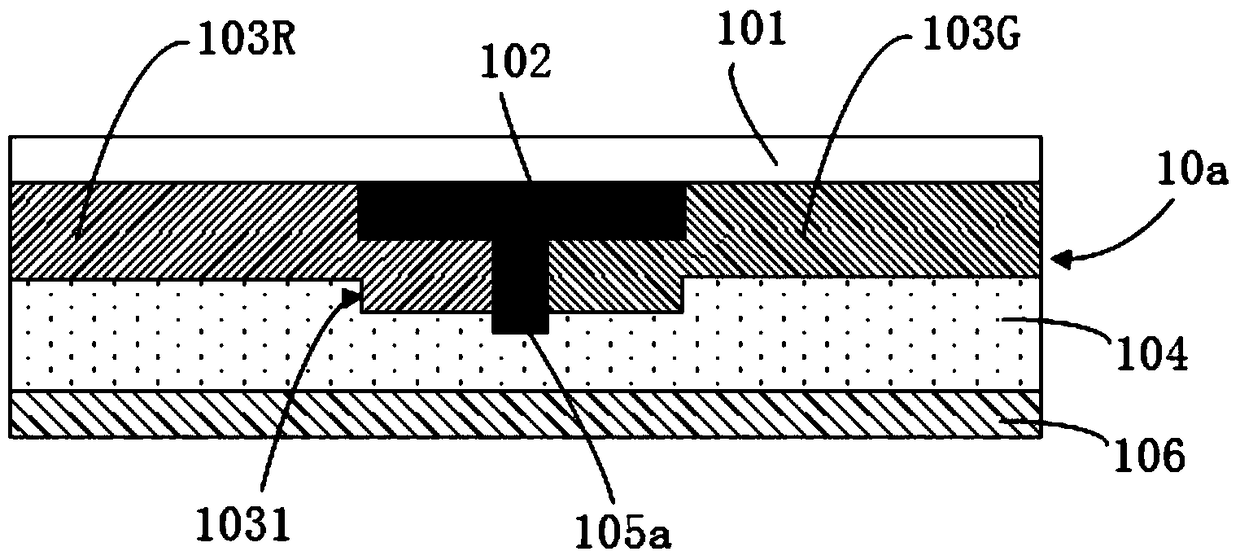
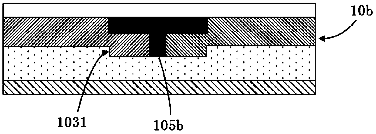
[0031] Such as figure 2 As shown, the color filter substrate 10a provided in this embodiment includes a glass substrate 101, a first black matrix 102 disposed on the glass substrate 101, and color-resist units arranged between the first black matrix 102 103R, 103G (the color resistance unit includes a red color resistance unit, a green color resistance unit and a blue color resistance unit, only the red color resistance unit 103R and the green color resistance unit 103G are shown in the figure) and the color resistance unit covering the color resistance The flat layer 104 on the units 103R and 103G (in some other embodiments, the flat layer 104 may not be provided), the color resistance units 103R and 103G have corner segment differences covering the first black matrix 102 1031. Wherein, the color filter substrate 10a further includes a second black matrix 105a, and the second black matrix 105a is vertically connected to the first black matrix 102 from the angular step diffe...
Embodiment 2
[0035] Such as Figure 5 As shown, the color filter substrate 10c provided in this embodiment includes a glass substrate 101, a first black matrix 102 disposed on the glass substrate 101, and color-resist units arranged between the first black matrix 102 103R, 103G (the color resistance unit includes a red color resistance unit, a green color resistance unit and a blue color resistance unit, only the red color resistance unit 103R and the green color resistance unit 103G are shown in the figure) and the color resistance unit covering the color resistance The flat layer 104 on the units 103R, 103G, the color-resist units 103R, 103G have an angular step difference portion 1031 covering the first black matrix 102 . Wherein, the color filter substrate 10c further includes a second black matrix 105c. Specifically, such as Figure 5 As shown, the second black matrix 105 c is arranged parallel to the first black matrix 102 , and is located between the angular step difference portio...
Embodiment 3
[0039] Such as Figure 7 As shown, the color filter substrate 10d provided in this embodiment includes a glass substrate 101, a first black matrix 102 disposed on the glass substrate 101, and color-resist units arranged between the first black matrix 102 103R, 103G (the color resistance unit includes a red color resistance unit, a green color resistance unit and a blue color resistance unit, only the red color resistance unit 103R and the green color resistance unit 103G are shown in the figure) and the color resistance unit covering the color resistance The flat layer 104 on the units 103R, 103G, the color-resist units 103R, 103G have an angular step difference portion 1031 covering the first black matrix 102 . Wherein, the color filter substrate 10d further includes a second black matrix 105d. Specifically, such as Figure 7 As shown, the second black matrix 105d is arranged parallel to the first black matrix 102 , which is located on the planar layer 104 and corresponds t...
PUM
 Abstract
Description
Claims
Application Information
 - R&D Engineer
- R&D Manager
- IP Professional
- Industry Leading Data Capabilities
- Powerful AI technology
- Patent DNA Extraction
Browse by: Latest US Patents, China's latest patents, Technical Efficacy Thesaurus, Application Domain, Technology Topic, Popular Technical Reports.
© 2024 PatSnap. All rights reserved.Legal|Privacy policy|Modern Slavery Act Transparency Statement|Sitemap|About US| Contact US: help@patsnap.com


