
Direct shear test system for anisotropy of geosynthetics and implementation method of direct shear test system

A technology of geosynthetics and anisotropy, which is applied in the direction of testing the strength of materials by applying a stable shear force, can solve the problems that the mechanical properties of the interface between geosynthetics and filling soil cannot be truly reflected, and achieve the solution of randomness and The effect of safety hazards

Active Publication Date: 2015-08-12
SHANXI PROVINCIAL RES INST OF COMM +1
View PDF5 Cites 12 Cited by
  • Summary
  • Abstract
  • Description
  • Claims
  • Application Information

AI Technical Summary

Problems solved by technology

[0005] The purpose of the present invention is to solve the technical problem that the interface mechanical properties of geosynthetics and filling soil obtained in the test in the prior art cannot truly reflect the actual engineering, and then provide a fully considered anisotropy of the mechanical properties of geosynthetics, An anisotropic direct shear test system for geosynthetics and its implementation method that effectively avoids serious discrepancies between the test values ​​in the current code and the actual mechanical properties of geosynthetics and the precise and controllable test process

Method used


Image

  • Direct shear test system for anisotropy of geosynthetics and implementation method of direct shear test system
  • Direct shear test system for anisotropy of geosynthetics and implementation method of direct shear test system
  • Direct shear test system for anisotropy of geosynthetics and implementation method of direct shear test system

Examples


Embodiment

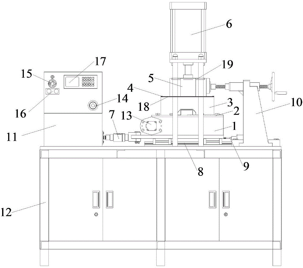
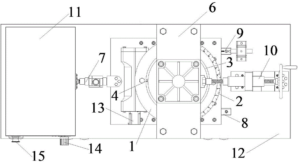
[0038] see figure 1 as well as figure 2 , an anisotropic direct shear test system for geosynthetics, comprising a slewing bearing 1, a dial 2, a lower shear box 3, a fixture 4, an upper shear box 5, a vertical loading device 6, a horizontal loading device 7, and guide rails 8. Displacement sensor 9, fixed support 10, cabinet 11, test bench 12, slewing bearing control device 13, vertical loading control device 14, horizontal loading control device 15, running indicator light 16, intelligent display control acquisition device 17, Geosynthetic material sample 18, bearing plate 19.

[0039] The lower shear box 3 is a semi-closed hollow cylinder with an inner diameter of 300mm, a thickness of 5mm and a height of 150mm.

[0040] The upper shear box 5 is a regular octagonal inscribed cylinder with an inner diameter of 200 mm, a thickness of 3 mm at the weakest point, and a height of 100 mm, and the difference between the octagonal outer diameter of the upper shear box 5 and the in...


PUM

PropertyMeasurementUnit
The inside diameter ofaaaaaaaaaa
Thicknessaaaaaaaaaa
Heightaaaaaaaaaa

Abstract

The invention discloses a direct shear test system for anisotropy of geosynthetics and an implementation method of the direct shear test system. The direct shear test system comprises a test bed rack, a slewing bearing, a dial, a lower shearing box, an upper shearing box, a vertical loading device, a horizontal loading device, a guide rail, a displacement sensor, a slewing bearing control device and a bearing plate, wherein the guide rail and the displacement sensor are arranged on the test bed rack; the dial and the slewing bearing control device are respectively arranged on the slewing bearing; the vertical loading device is arranged on the slewing bearing sequentially through the bearing plate, the upper shearing box and the lower shearing box; the lower shearing box is driven to rotate by the slewing bearing; the cross section of a geosynthetic which needs to be subjected to a shear test is round, and the diameter of the geosynthetic is same as the outer diameter of the lower shearing box; the horizontal loading device is connected with the slewing bearing and can slide on the guide rail. According to the direct shear test system for the anisotropy of the geosynthetics, the technical problem that the engineering practice cannot be truly reflected by the interface mechanical characteristics of the geosynthetics and fillings which are obtained in the test in the prior art is solved.

Description

technical field [0001] The invention belongs to the field of mechanical performance test of geosynthetics, and relates to an anisotropic direct shear test system of geosynthetics and an implementation method thereof, in particular to an anisotropic direct shear of geosynthetics with reinforced soil technology in loess gully areas Experimental system and its implementation method. Background technique [0002] Geosynthetics are made of artificially synthesized polymers (such as plastics, chemical fibers, synthetic rubber, etc.) The role of soil. It mainly includes geotextiles, geogrids, geomembranes, geotechnical special materials and geocomposites, fiberglass mesh, geomats and other types. [0003] At present, both "Testing Regulations for Geosynthetics" (SL 235-2012) and "Testing Regulations for Geosynthetics for Highway Engineering" (JTG E50-2006) both refer to the direct shear test of geosynthetics. However, there are still many problems in the direct shear test of geo...

Claims


Application Information

Patent Timeline
IPC IPC(8): G01N3/24
Inventor 张军刘晓赵建斌薛春明
Owner SHANXI PROVINCIAL RES INST OF COMM
Learn More