Geosynthetics anisotropism drawing test system and method
A technology of geosynthetics and pull-out test, which is applied in the direction of applying stable tension/compression to test the strength of materials to achieve the effect of solving randomness
Active Publication Date: 2015-08-12
山西省交通科技研发有限公司
View PDF7 Cites 10 Cited by
- Summary
- Abstract
- Description
- Claims
- Application Information
AI Technical Summary
Benefits of technology
This patented technology describes a new type of testing machine that can be pulled out from different directions without changing its shape or dimensions. Its technical effect lies in ensuring accurate results for tensile strength measurements on artificially made materials such as concrete (cement).
Problems solved by technology
This patents discuss various issues with existing testing techniques for geosynthesis clay products used in construction projects or road works. These technical problem addressed include lacking consistence between different measurements conducted during manufacturing processes, potential variations that can affect the strength of these products over time, difficulty understanding how they behave under loadings caused by traffic flow, and potentially unsafe conditions associated with their use.
Method used
View moreImage
Smart ImageViewing Examples
Examples
Embodiment
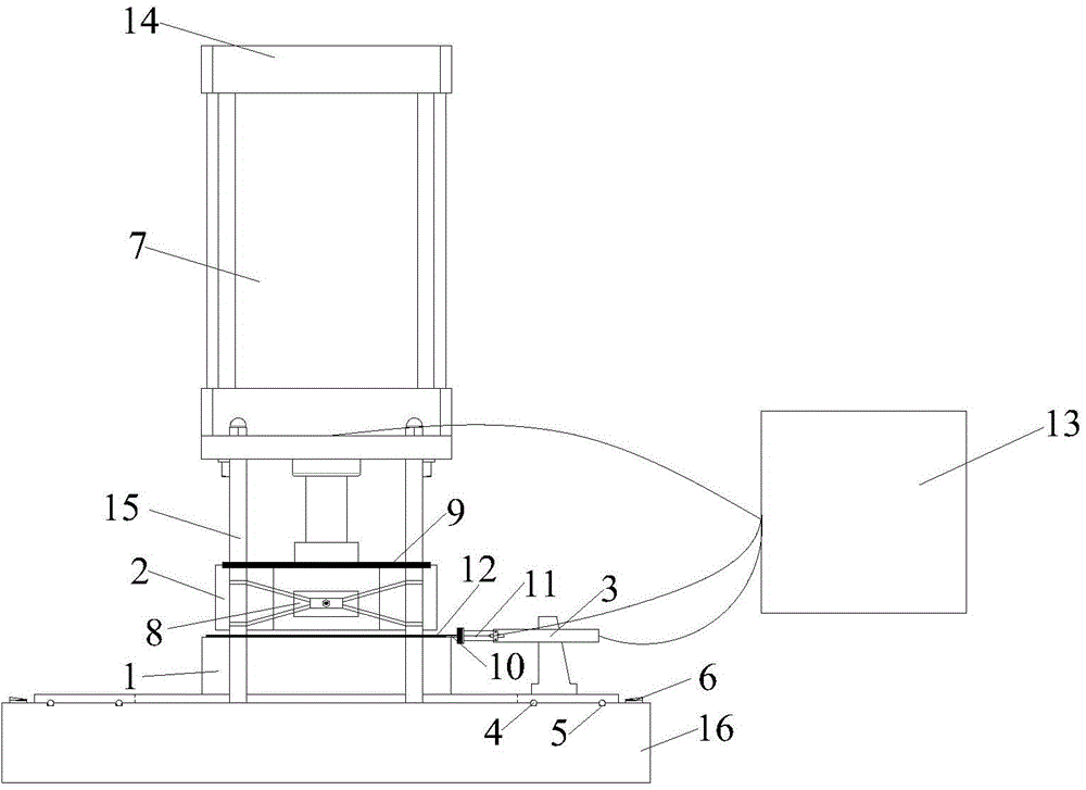
[0052] see figure 1 as well as figure 2 , a kind of geosynthetic material anisotropic drawing test system, comprises lower test box 1, upper test box 2, drawing loading device 3, sliding ball 4, guide rail 5, dial 6, vertical loading device 7, fixed support Seat 8 , bearing plate 9 , fixture 10 , displacement sensor 11 , signal acquisition control device 13 , reaction force frame 14 , reaction force bar 15 and test bench 16 .
Login to View More PUM
| Property | Measurement | Unit |
|---|---|---|
| The inside diameter of | aaaaa | aaaaa |
| Thickness | aaaaa | aaaaa |
| Height | aaaaa | aaaaa |
Abstract
The invention discloses a geosynthetics anisotropism drawing test system and method. The system comprises a test bed, a lower test box, an upper test box, a drawing loading device, a guide rail, a dial, a vertical loading device, a displacement sensor, a signal collection control device, and a jig for clamping a geosynthetics sample, wherein the circular dial, the guide rail and the lower test box are arranged on the upper surface of the test bed, the drawing loading device is arranged on the guide rail and slides freely on the guide rail; the displacement sensor for measuring the displacement of the jib is arranged on the drawing loading device; the vertical loading device, the upper test box, the geosynthetics sample and the lower test box are arranged on the test bed from up to bottom in sequence; the signal collection control device is connected with the drawing loading device, the displacement sensor and the vertical loading device. The test system and method have the advantages that the occurrence that the tested value of a geosynthetics anisotropism drawing test is seriously inconsistent with the actual engineering stress characteristic is avoided and the test process is accurate and controllable.
Description
Login to View More Claims
Login to View More Application Information
Patent Timeline
 Owner 山西省交通科技研发有限公司
Features
- R&D
- Intellectual Property
- Life Sciences
- Materials
- Tech Scout
- Unparalleled Data Quality
- Higher Quality Content
- 60% Fewer Hallucinations
Learn More Browse by: Latest US Patents, China's latest patents, Technical Efficacy Thesaurus, Application Domain, Technology Topic, Popular Technical Reports.
© 2025 PatSnap. All rights reserved.Legal|Privacy policy|Modern Slavery Act Transparency Statement|Sitemap|About US| Contact US: help@patsnap.com


