
Valve rocker mounting mechanism and gasoline engine thereof

A technology of valve rocker arm and installation mechanism, applied in the direction of machine/engine, valve device, mechanical equipment, etc., can solve the problems of wasting fuel, inaccurate movement, and lax closing, etc., so as to reduce the working load of the timing shaft and ensure smooth operation. The effect of stability and accuracy, simple manufacturing process

Active Publication Date: 2015-08-12
SUZHOU ERMA MECHNICAL & ELECTRICAL
View PDF6 Cites 6 Cited by
  • Summary
  • Abstract
  • Description
  • Claims
  • Application Information

AI Technical Summary

Problems solved by technology

The existing rocker arm assembly cannot efficiently utilize the power transmitted by the power arm of the valve rocker arm, and increases the wear of the contact surface, resulting in the problems that the existing intake and exhaust valve assemblies are not tightly closed, inaccurate and unsmooth. , gas distribution is inaccurate, wastes fuel, reduces efficiency, and affects the normal operation of gasoline engines

Method used


Image

  • Valve rocker mounting mechanism and gasoline engine thereof
  • Valve rocker mounting mechanism and gasoline engine thereof
  • Valve rocker mounting mechanism and gasoline engine thereof

Examples


Embodiment Construction

[0023] The above solution will be further described below in conjunction with specific embodiments. It should be understood that these examples are used to illustrate the present invention and not to limit the scope of the present invention. The implementation conditions used in the examples can be further adjusted according to the conditions of specific manufacturers, and the implementation conditions not indicated are usually the conditions in routine experiments.

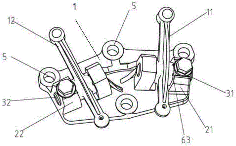
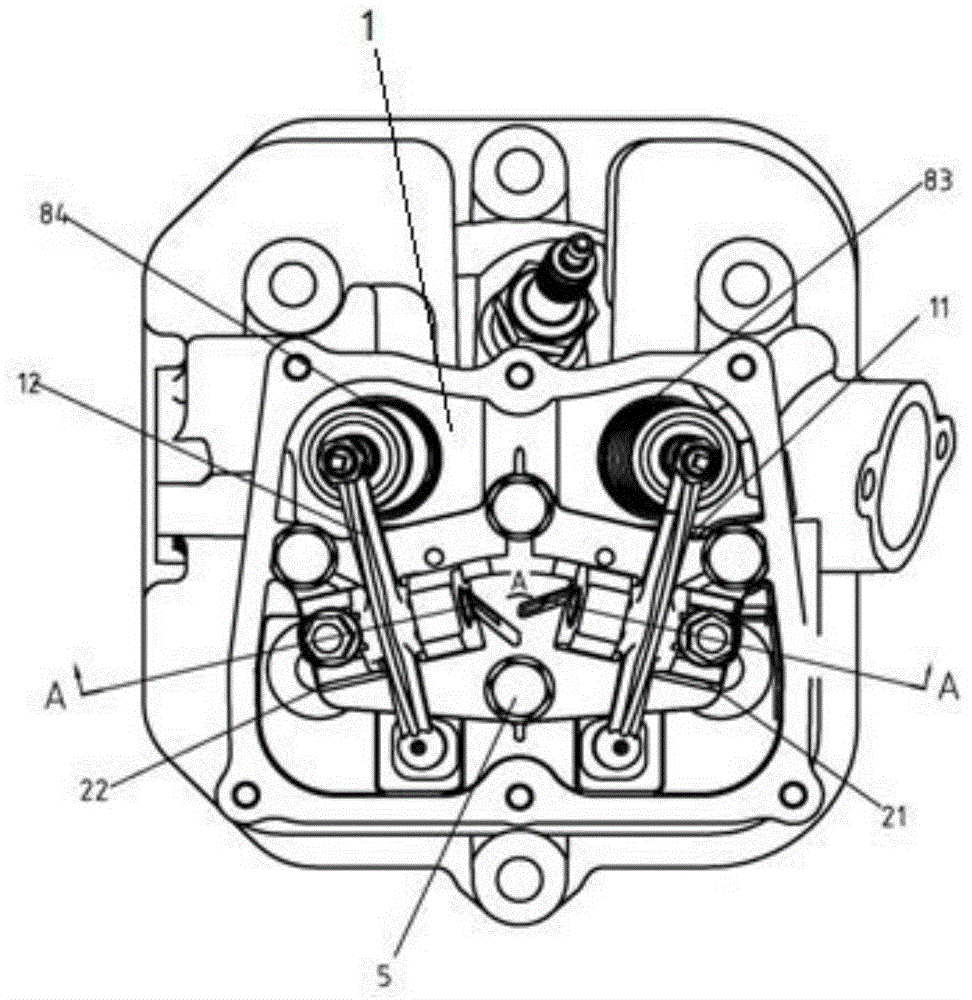
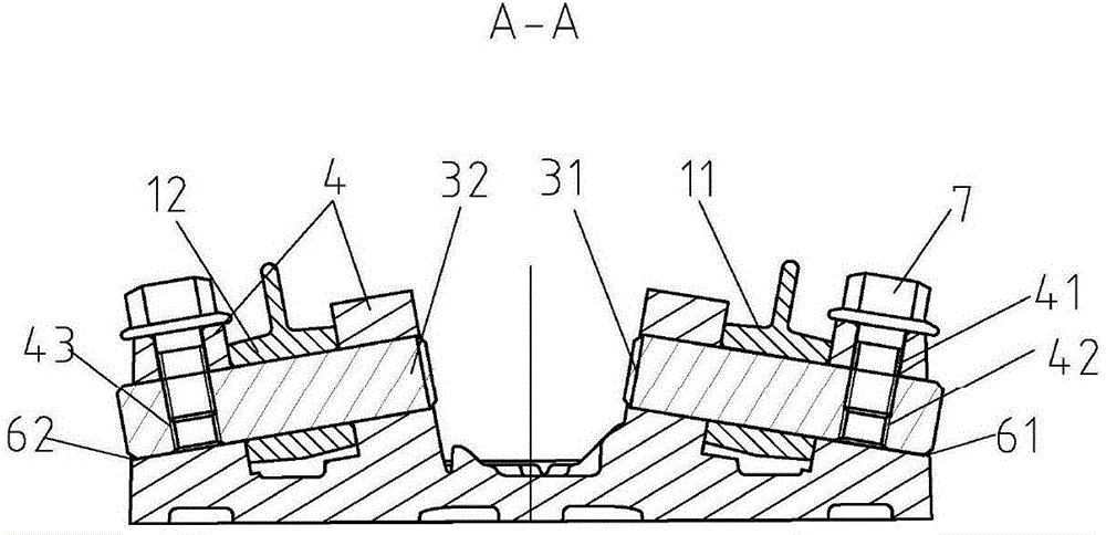
[0024] see Figure 1-5 , is a structural schematic diagram of an embodiment of the present invention, providing a valve rocker arm installation mechanism, which includes a valve rocker arm installation seat 1, and a valve rocker arm installation seat 1 is provided with a rocker arm 11 for installing an intake valve and an exhaust valve rocker The intake valve rocker arm seat 21 and the exhaust valve rocker arm seat 22 of the arm 12, the intake valve rocker arm 11 and the exhaust valve rocker arm 12 are respectiv...


PUM


Abstract

The invention discloses a valve rocker mounting mechanism. The valve rocker mounting mechanism comprises a valve rocker mounting seat, wherein an intake valve rocker seat and an exhaust valve rocker seat are arranged on the valve rocker mounting seat, the intake valve rocker seat is used for mounting an intake valve rocker, and the exhaust valve rocker seat is used for mounting an exhaust valve rocker; the intake valve rocker and the exhaust valve rocker are hinged to the intake valve rocker seat and the exhaust valve rocker seat by an intake valve rocker shaft and an exhaust valve rocker shaft; the intake valve rocker is used for driving a contact surface, which corresponds to the top of an intake valve rod, to be respectively vertical to the corresponding axis of the intake valve rod, and the exhaust valve rocker is used for driving a contact surface, which corresponds to the top of an exhaust valve rod, to be respectively vertical to the corresponding axis of the exhaust valve rod; an included angle is formed between the axis of an axle hole of the intake valve rocker seat and a junction surface of the valve rocker mounting seat and a cylinder head, and an included angle is formed between the axis of an axle hole of the exhaust valve rocker seat and the junction surface of the valve rocker mounting seat and the cylinder head; an included angle is formed between the axis of an axle hole of the intake valve rocker shaft and the axis of an axle hole of the exhaust valve rocker shaft, and the intake valve rocker seat and the exhaust valve rocker seat are symmetrically arranged on the valve rocker mounting seat. The valve rocker mounting mechanism and a gasoline engine thereof, which are provided by the invention, have the advantages that the power transferred by the valve rockers can be highly efficiently utilized, the abrasion of the contract surfaces is reduced, and the workload of a valve driving mechanism is reduced.

Description

technical field [0001] The invention relates to the technical field of power equipment, in particular to a valve rocker arm installation mechanism and a gasoline engine. Background technique [0002] Gasoline engine is a kind of power machinery that uses gasoline as fuel. It is composed of cylinder, crank connecting rod mechanism, gas distribution system, oil supply system, lubrication system and ignition system. General-purpose gasoline engines refer to reciprocating piston gasoline engines that are widely used in addition to vehicles and aviation. The general power is less than 20kW. The general-purpose gasoline engine is characterized by simple structure, easy operation, and low cost. It is mainly used for agricultural and forestry plant protection machinery, garden machinery, small machinery, generator sets, construction machinery, fire-fighting series machinery, recreational karts, water power and aviation model power, etc. [0003] The gas distribution system of the g...

Claims


Application Information

Patent Timeline
Patent Type & Authority Applications(China)
IPC IPC(8): F01L1/18
CPCF01L1/18
Inventor 马云峰
Owner SUZHOU ERMA MECHNICAL & ELECTRICAL
Learn More