
Machine head device of claw cutter

A technology of claw cutting machine and machine head, which is applied in the direction of metal processing, etc., can solve the problems of increasing maintenance rate, reducing production efficiency, increasing production cost, etc., and achieves the effects of improving production efficiency, reducing use and maintenance costs, and facilitating replacement

Inactive Publication Date: 2015-08-12
杨术本
View PDF0 Cites 0 Cited by
  • Summary
  • Abstract
  • Description
  • Claims
  • Application Information

AI Technical Summary

Problems solved by technology

[0002] At present, the design of the cutter head of ordinary claw cutting machine is relatively simple. First, the cutter head is directly welded to death, which makes it inconvenient to replace the blade. Second, it is fastened by bolts. Cutting the damaged blade increases the maintenance rate, increases the production cost, increases the labor intensity of the operator, and reduces the production efficiency

Method used


Image

  • Machine head device of claw cutter
  • Machine head device of claw cutter

Examples


Embodiment Construction

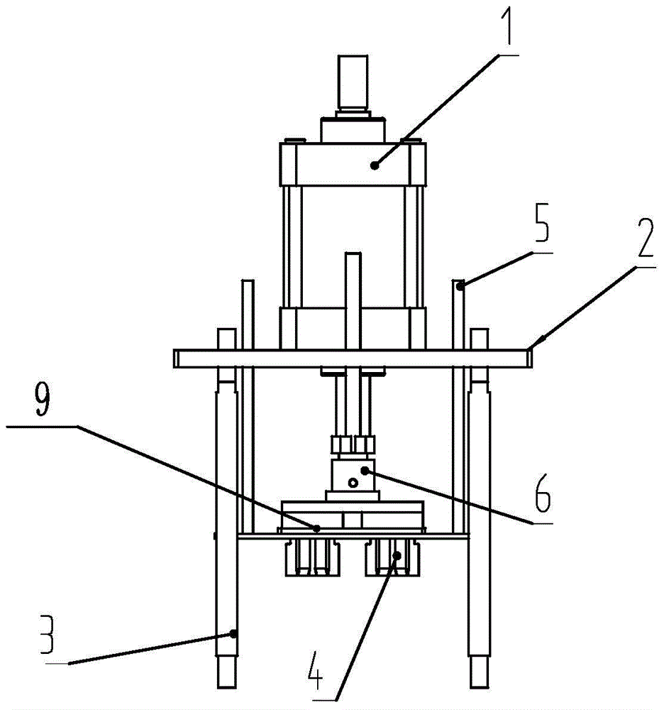
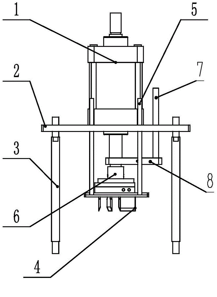
[0010] like figure 1 , 2 As shown, the present invention comprises cylinder 1, frame plate 2, support rod 3, cutter 4, guide rod 5, cutter holder sleeve 6, limit rod 7, limit connection lock plate 8, cutter holder 9, described The upper side of the frame plate 2 is provided with a cylinder 1, the four corners of the frame plate 2 are respectively provided with support rods 3, the lower side of the cylinder 1 is provided with a cutter frame 9, and the cutter frame 9 is connected to the cylinder by the cutter frame sleeve 6. 1 connection, the four corners of the cutter frame 9 are provided with guide rods 5, the guide rods 5 penetrate the frame plate 2 upwards, and the limit connection lock plate 8 is provided above the cutter frame sleeve 6, and the limit connection lock plate 8 is fitted on the lower side of the cylinder 1, the other end of the limit connecting plate is fitted and fixed with the limit rod 7, the limit rod 7 penetrates the frame plate 2 upward, and the lower s...


PUM


Abstract

The invention discloses a machine head device of a claw cutter. The machine head device comprises a cylinder, a frame plate, support rods, a cutter, guide rods, a cutter frame sleeve head, a limiting rod, a limiting connecting lock plate and a cutter frame, wherein the cylinder is arranged at the upper side of the frame plate; the support rods are respectively arranged at the four corners of the frame plate; the cutter frame is arranged at the lower side of the cylinder, and is connected with the cylinder through the cutter frame sleeve head; the guide rods are arranged at the four corners of the cutter frame, and upwards penetrate through the frame plate; the limiting connecting lock plate is arranged above the cutter frame sleeve head, and coats the lower side of the cylinder; the other end of the limiting connecting plate is in fixed coating with the limiting rod; the limiting rod upwards penetrates through the frame plate; and the cutter is arranged at the lower side of the cutter frame. The machine head device of the claw cutter has the following beneficial effects: the cutter bit fixation is realized by using the cutter frame and the cutter frame sleeve head; the blade replacement convenience is guaranteed; the use and maintenance costs are reduced; and the production efficiency is improved.

Description

technical field [0001] The invention relates to a cutter head fixing device, in particular to a claw cutting machine head device. Background technique [0002] At present, the design of the cutter head of ordinary claw cutting machine is relatively simple. First, the cutter head is directly welded to death, which makes it inconvenient to replace the blade. Second, it is fastened by bolts. Cutting damages the blade, increases the maintenance rate, increases the production cost, increases the labor intensity of the operator, and reduces the production efficiency. Contents of the invention [0003] The purpose of the present invention is to provide a claw cutting machine head device that not only realizes the fixing and fastening of the cutter head, but also ensures the convenience of blade replacement. [0004] In order to achieve the above object, the technical solution of the present invention includes a cylinder, a frame plate, a support rod, a cutter, a guide rod, a cut...

Claims


Application Information

Patent Timeline
Patent Type & Authority Applications(China)
IPC IPC(8): B26D7/26
Inventor 杨术本程显铭李政
Owner 杨术本
Learn More