Hydraulic drawing pad of a drawing press and method of operating a hydraulic drawing pad

A hydraulic deep drawing and press technology, which is applied to fluid pressure actuating devices, mechanical equipment, servo meter circuits, etc., can solve the problems of expensive hydraulic deep drawing pads and inability to generate metal sheet holding force.

Active Publication Date: 2017-04-19
SCHULER PRESSEN GMBH & CO KG
View PDF8 Cites 0 Cited by
  • Summary
  • Abstract
  • Description
  • Claims
  • Application Information

AI Technical Summary

Problems solved by technology

The working chamber and the piston area cannot be made arbitrarily small, since the fluid pressure would then not be able to generate sufficient sheet metal holding force
If higher accelerations or velocities of the piston or sheet metal retaining ring are required, the motor / pump unit must be sized to exhibit adequate dynamics, thereby making the hydraulic drawing pad considerably more expensive

Method used


Image

  • Hydraulic drawing pad of a drawing press and method of operating a hydraulic drawing pad
  • Hydraulic drawing pad of a drawing press and method of operating a hydraulic drawing pad
  • Hydraulic drawing pad of a drawing press and method of operating a hydraulic drawing pad

Examples


Embodiment Construction

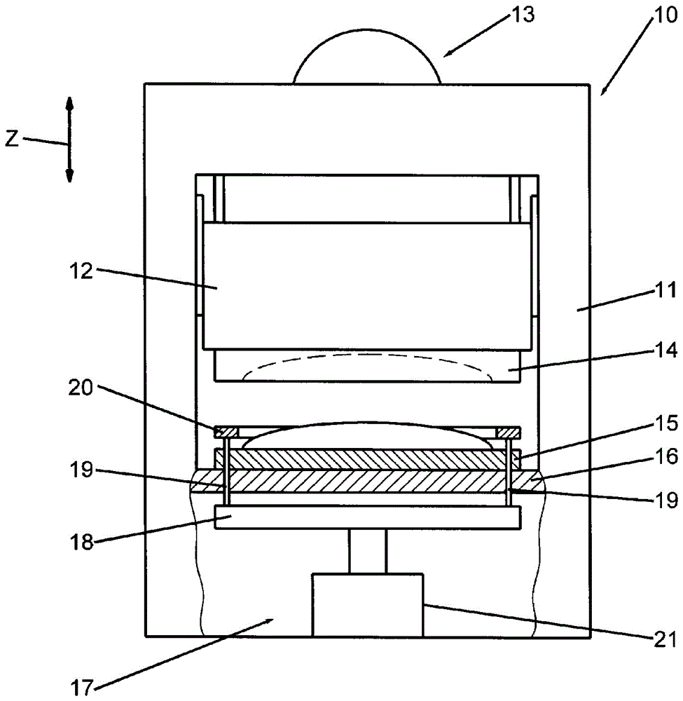
[0036] figure 1 is a schematic illustration of a drawing press 10 with a press frame 11 . The ram 12 is arranged on the press frame 11 so as to be movable in the working direction Z, for example in the vertical direction. A press drive 13 is arranged to move the ram 12 . A first tool 14 is arranged on the ram 12 . A second tool 15 is supported at a distance from the first tool by the press frame 11 , for example by means of a press table 16 .

[0037] Furthermore, the drawing press 10 includes a hydraulic drawing pad 17 . The hydraulic drawing pad 17 is located on the side of the second tool 15 facing away from the first tool 14 , ie, according to the example, under the press table 16 . The floating plate 18 is associated with the hydraulic drawing pad 17 . Arranged on the floating plate 18 is a pressure rod 19 which extends from the floating plate 18 to the second tool 15 . According to the example, the pressing rod 19 extends through the press table 16 and through and / ...


PUM


Abstract

A hydraulic drawing cushion (17) for a drawing press (10) includes at least one hydraulic cylinder (21) comprising a piston rod (27) that causes a total force (G) to act on the metal sheet holding ring (20). The hydraulic cylinder (21) comprises a hydraulic work circuit (37) to generate a hydraulic work force (A) in a work direction (Z) to act on a ring part (28) to which a force can be applied on both sides. Independently, a spring force (F) acts on the piston (26). The spring force (F) is neither controlled nor adjusted, but is preset. Preferably, the spring force (F) is exclusively a function of the position or location of the piston (26) relative to the cylinder housing (25). The total force (G) acting on the piston (26) results from the addition of the vectors of the work force (A) and the spring force (F).

Description

technical field [0001] The invention relates to a hydraulic drawing pad of a drawing press and also to a method for operating said drawing pad. Background technique [0002] Hydraulic drawing cushions have been used on drawing presses for a long time. During a drawing operation, a drawing press clamps a sheet of metal between a first tool and a second tool. The two tools move relative to each other during the working stroke. During the relative movement, the sheet metal is drawn over the tool dies and pressed between the two tool dies of the two tools. During deep drawing of a sheet metal, the drawing pad provides the necessary holding force against the sheet metal. [0003] Such a hydraulic drawing mat is known, for example, from publication DE 10 2006 058 630 A1. A hydraulic drawing pad includes a hydraulic cylinder having a cylinder housing and a piston that can move back and forth therein. The piston divides the interior of the cylinder into two working chambers. T...

Claims


Application Information

Patent Timeline
Patent Type & Authority Patents(China)
IPC IPC(8): B21D24/08
CPCB21D24/02B21D24/14F15B2015/206F15B2211/20515F15B2211/20538F15B2211/20561F15B2211/27F15B2211/625F15B2211/6651F15B2211/6653F15B2211/6654F15B2211/7054F15B2211/75F15B2211/76F15B2211/765B21D24/04B21D24/10
Inventor D.赖施M.米克利施M.里希特
Owner SCHULER PRESSEN GMBH & CO KG
Why Eureka
Try Eureka