
Heating tube with descaling device

A heating tube and electric heating tube technology, applied in the field of heating tubes, can solve the problems of difficulty in cleaning, no dirt, short service life, etc.

Inactive Publication Date: 2015-08-12
ZHENJIANG BOLIN PHOTOELECTRIC TECH
View PDF10 Cites 10 Cited by
  • Summary
  • Abstract
  • Description
  • Claims
  • Application Information

AI Technical Summary

Problems solved by technology

[0002] The existing electric heating tube generally includes a glass tube body, and the outer wall of the glass tube body or the inner wall of the glass tube is covered with a coating film. On the one hand, the traditional electric heating tube has an unreasonable structure and a short service life. On the other hand, the working In the process, the dirt generated by the long-term use of the electric heating tube is difficult to be cleaned because there is no special cleaning structure, which reduces people's demand for its use

Method used


Image

  • Heating tube with descaling device
  • Heating tube with descaling device

Examples


Embodiment 1

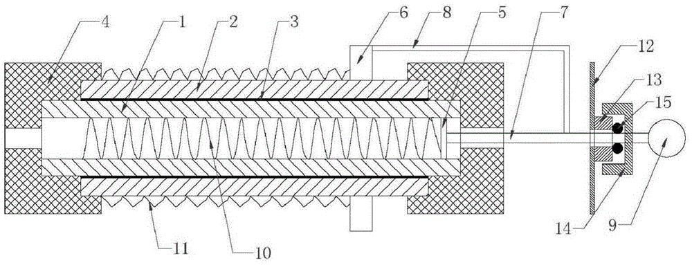
[0020] Such as figure 1 As shown, the electric pipe with descaling device of the present invention includes a pipe body 1, and a heating element 3 is arranged outside the pipe body 1, and the heating element 3 is an external burner or electrothermal coating; said pipe body 1 is a No. 1 glass tube, No. 1 glass tube and the electrothermal coating on the outside of No. 1 glass tube 1 form the main body of the electrothermal tube. An internal scraper 5 is placed in the inner cavity of the tube body 1. The internal scraper 5 is a hollow scraper. 5 is driven by a reciprocating driving part to move along a straight line, and the lower end of the internal scraper 5 is fixedly connected with an internal descaling spring 10 whose outer diameter is compatible with the inner cavity of the tube body 1; the main body of the electric heating tube is installed in a housing 12 Inside, a guide block 13 with external thread is fixedly installed on the outer wall of the housing 12, and a nut 14 i...

Embodiment 2

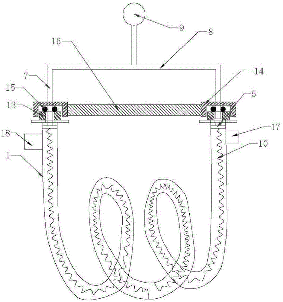
[0023] Such as figure 2 As shown, the electric heating tube with descaling device of the present invention includes a No. 1 glass tube and a coating 3 outside the No. 1 glass tube. An internal scraper 5 is arranged in the inner cavity of the No. 1 glass tube. The reciprocating driving part drives it to move in a straight line; said driving part is a pull rod 7 connected to the upper end of the internal scraper 5, and the pull rod 7 extends out of the No. 1 glass tube. The upper end of the pull rod 7 has an operating end 9, and the operating end 9 It can be operated manually or driven by a power device; the said pipe body 1 is a U-shaped pipe or a coiled pipe, and the first and last ends of the pipe body 1 are respectively fixed and installed through the installation ends, and a piece with a Outer threaded guide block 13, a nut 14 is installed outside each guide block 13, sealing ring 15 is all pressed between the upper end surface of each block guide block 13 and the inner en...


PUM


Abstract

The invention discloses a heating tube with a descaling device. The heating tube comprises a tube body. The external part of the tube body is provided with a heating element. An internal scrapping plate is arranged in the internal cavity of the tube body. The internal scrapping plate is driven to move along a straight line by a driving component capable of moving in a reciprocating way. The lower end of the internal scrapping plate is fixedly connected with an internal descaling spring of which the external diameter is adaptive to the internal cavity of the tube body. With application of the structure, dirt on glass tubes can be cleaned by the internal scrapping plate which can be driven to linearly move in the reciprocating way by the driving component moving in the reciprocating way, the arranged descaling spring is good for descaling and a coated film is arranged between the center glass tube and the external glass tubes so that the service life is enhanced and the heating effect is enhanced. The structural setting is simple and reasonable, and the cleaning and use effects are quite good so that the heating tube with the descaling device is favorable for popularization and use.

Description

technical field [0001] The invention relates to a heating pipe, in particular to a heating pipe with a descaling device. Background technique [0002] The existing electric heating tube generally includes a glass tube body, and the outer wall of the glass tube body or the inner wall of the glass tube is covered with a coating film. On the one hand, the traditional electric heating tube has an unreasonable structure and a short service life. On the other hand, the working In the process, the dirt generated by the long-term use of the electric heating tube makes it difficult to be cleaned because there is no special cleaning structure, which reduces people's demand for its use. Contents of the invention [0003] The technical problem to be solved by the present invention is to provide a heating pipe with a descaling device that has a reasonable structure, long service life and can completely remove the dirt on the pipe wall. [0004] In order to solve the above-ment...

Claims


Application Information

Patent Timeline
IPC IPC(8): B08B9/023B08B9/043H05B3/02H05B3/42
CPCB08B9/023B08B9/0436H05B3/02H05B3/42H05B2203/013
Inventor 夏致俊
Owner ZHENJIANG BOLIN PHOTOELECTRIC TECH
Learn More