
A Method for Determining Dynamic Parameters of Cracked Gear-Rotor System Considering Extended Meshing

A gear rotor, parameter determination technology, applied in electrical digital data processing, special data processing applications, instruments, etc., can solve the problems of early meshing, extended meshing, and high time-varying meshing stiffness

Active Publication Date: 2017-12-05
NORTHEASTERN UNIV LIAONING
View PDF3 Cites 0 Cited by
  • Summary
  • Abstract
  • Description
  • Claims
  • Application Information

AI Technical Summary

Problems solved by technology

However, in practice gears are elastic, and this elasticity (especially in the presence of cracks) may cause the gear to mesh earlier and later than the theoretical contact point (calculated by existing analytical methods that do not consider extended meshing) out, i.e., prolonged meshing phenomenon
In addition, since two simultaneously meshing teeth share one tooth body, the time-varying meshing stiffness in the double-tooth meshing area will be much higher than the actual stiffness

Method used


Image

  • A Method for Determining Dynamic Parameters of Cracked Gear-Rotor System Considering Extended Meshing
  • A Method for Determining Dynamic Parameters of Cracked Gear-Rotor System Considering Extended Meshing
  • A Method for Determining Dynamic Parameters of Cracked Gear-Rotor System Considering Extended Meshing

Examples


Embodiment Construction

[0071] The specific embodiments of the present invention will be described in detail below in conjunction with the accompanying drawings.

[0072] A method for determining the dynamic parameters of a cracked gear-rotor system considering extended meshing, such as figure 1 shown, including the following steps:

[0073] Step 1: Obtain the basic parameters of the healthy gear and the basic parameters and crack parameters of the cracked gear.

[0074] In this embodiment, the basic parameters of the healthy gear and the basic parameters of the cracked gear are obtained as shown in Table 1:

[0075] Table 1 Basic parameters of healthy gears and basic parameters of cracked gears

[0076]

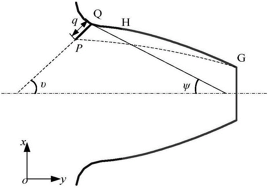
[0077] Schematic diagram of crack gear figure 2 Shown: the geometric parameters of the crack (q, υ, ψ), where q represents the depth of the crack, υ represents the direction of crack propagation, ψ represents the starting position of the crack, G is the intersection point of the addendum cir...


PUM


Abstract

The invention relates to a method for determining the dynamic parameters of a cracked gear-rotor system considering extended meshing. The method is to obtain the basic parameters of healthy gears, the basic parameters of cracked gears and the crack parameters, and establish a gear meshing stiffness model including matrix stiffness. The finite element method is used to calculate the matrix stiffness of the driving wheel and the driven wheel of the gear, determine the gear matrix stiffness correction coefficient of the meshing stiffness model including the matrix stiffness, and use the method of solving the gear transmission error to determine the tooth deformation of the gear. The time-varying meshing stiffness of the gear is obtained, the basic parameters of the shaft and bearing of the gear-rotor system are obtained, and the stiffness matrix K of the gear-rotor system is obtained. According to the stiffness matrix K of the gear-rotor system, the vibration response analysis model of the gear-rotor system considering the extended meshing is constructed. Determine system vibration response results for healthy and cracked gears.

Description

technical field [0001] The invention belongs to the technical field of mechanical dynamics, and in particular relates to a method for determining dynamic parameters of a cracked gear-rotor system considering extended meshing. Background technique [0002] The calculation of time-varying mesh stiffness is an important field in the dynamics research of cracked gears. Many researchers have proposed models for calculating time-varying mesh stiffness. There are mainly the following methods: method 1: finite element method, this method is the most widely used, because it has high accuracy and can simulate complex gear structures at the same time, based on the finite element model, the time-varying meshing stiffness can be passed at the theoretical contact point It can be realized by applying a meshing force representing the load transmitted by the gear or by establishing a contact element between the meshing teeth, but this method has low computational efficiency; method 2: analyt...

Claims


Application Information

Patent Timeline
Patent Type & Authority Patents(China)
IPC IPC(8): G06F17/50
Inventor 马辉冯然娇逄旭闻邦椿
Owner NORTHEASTERN UNIV LIAONING
Learn More