
System And Method For Avoiding DC Bias In A Homodyne Receiver

A receiver, homodyne technology, used in radio wave measurement systems, using re-radiation, radio wave reflection/re-radiation, etc., can solve problems such as performance degradation

Inactive Publication Date: 2015-08-05
FORD GLOBAL TECH LLC
View PDF4 Cites 2 Cited by
  • Summary
  • Abstract
  • Description
  • Claims
  • Application Information

AI Technical Summary

Problems solved by technology

The result may be reduced performance of functions that rely on the radar system to detect objects

Method used


Image

  • System And Method For Avoiding DC Bias In A Homodyne Receiver
  • System And Method For Avoiding DC Bias In A Homodyne Receiver
  • System And Method For Avoiding DC Bias In A Homodyne Receiver

Examples


Embodiment Construction

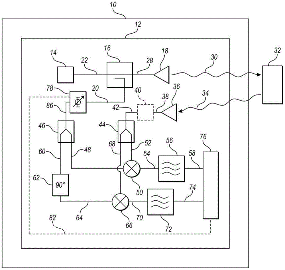
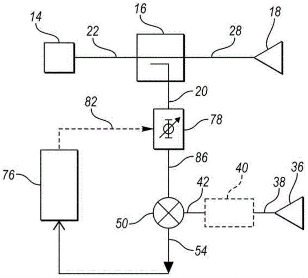
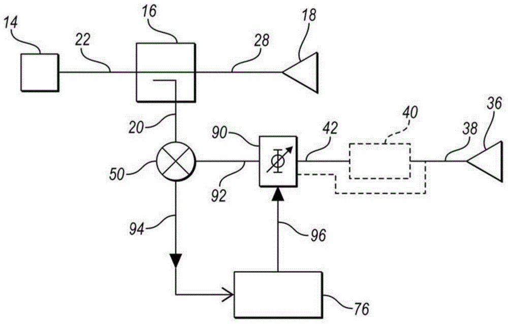
[0016] Embodiments of the present disclosure are described herein. It should be understood, however, that the embodiments disclosed herein are merely examples and that other embodiments may take various and alternative forms. The figures are not necessarily to scale; some features may be exaggerated or minimized to show details of particular components. Therefore, specific structural and functional details disclosed herein are not to be interpreted as limiting, but merely as a representative basis for teaching one skilled in the art to variously employ the present invention. As will be understood by persons of ordinary skill in the art, various features shown and described with reference to any one of the figures may be combined with features shown in one or more other figures to produce Examples shown or described. Combinations of features shown provide representative embodiments for typical applications. However, various combinations and modifications of the features cons...


PUM


Abstract

A homodyne radar system includes a mixer that outputs a signal having a mixer output frequency that is a frequency difference between two input signals. When the frequency difference is small, low frequency noise may mask the actual signal. A variable phase shifter is added to one of the mixer inputs to change the phase at a predetermined rate of change. The phase shifter shifts the frequency of the input signal so that the mixer output frequency is offset by the predetermined rate. The low frequencies are mapped to frequencies that are above the noise frequencies. The phase shift may be achieved by adding a constant phase at predetermined time intervals. The sampling frequency for the resulting signal may need to be increased to accommodate the higher frequencies.

Description

technical field [0001] The present application generally relates to the operation of avoiding low frequency noise in radar systems. Background technique [0002] Radar systems may be used in motor vehicles for many purposes. For example, radar systems enable safety features such as collision warning and adaptive cruise control. The effectiveness of such systems may depend on the performance of the radar system. Radar works by transmitting electromagnetic waves reflected off objects back to the radar receiver. The reflected signal may vary in frequency relative to the transmitted signal. Radar electronics using a mixer may generate a signal that is the difference in frequency of the transmitted signal and the received signal. This frequency difference can then be processed to calculate the distance and relative velocity of the object. [0003] A homodyne receiver sub-converts the radar signal directly to baseband frequency without first converting the signal to any inter...

Claims


Application Information

Patent Timeline
IPC IPC(8): G01S7/285G01S7/41G01S13/931
CPCG01S7/02G01S7/038G01S7/354G01S13/36G01S13/40G01S13/931G01S13/343G01S13/584G01S7/358G01S7/03
Inventor 詹姆斯·保罗·艾博林
Owner FORD GLOBAL TECH LLC
Learn More