


Quick Research
Generate reliable direction feasibility study reports for your R&D in just a few steps.

Technical Q&A
Discover and master advanced knowledge NOW. Basics, ideas, possibilities, all at once.

Find Solutions
As an expert in R&D theories, this can generate solutions to your technical problems instantly.

Evaluate Feasibility
Analyze your overall solution with one click, know your potential R&D risks in advance.

Monitor Landscape
Get weekly tech updates, stay abreast of the latest tech innovations and key insights.
No-mold casting method for preventing sand bonding and prefabricated part
A technology of moldless casting and prefabricated parts, which is applied in the direction of casting molding equipment, casting molds, and casting mold components. Concession, the effect of increasing the casting speed
- Summary
- Abstract
- Description
- Claims
- Application Information
AI Technical Summary
Problems solved by technology
Method used
Image

Examples
Embodiment 1
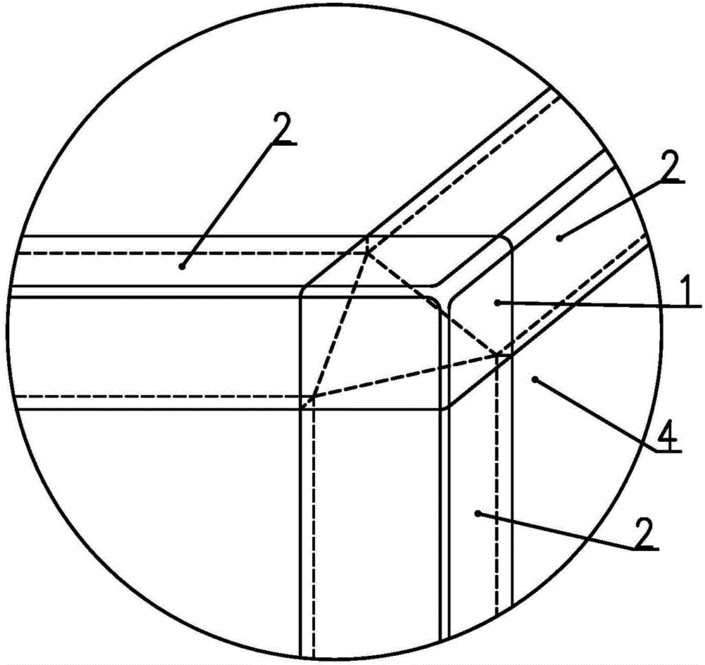
[0040] Example 1: See Figure 7 As shown, point A of the moldless sand mold is a place where sand is easy to stick during the casting process. The method in the present invention can be used to solve the problem of sticking sand at point A. The specific method steps are as follows:
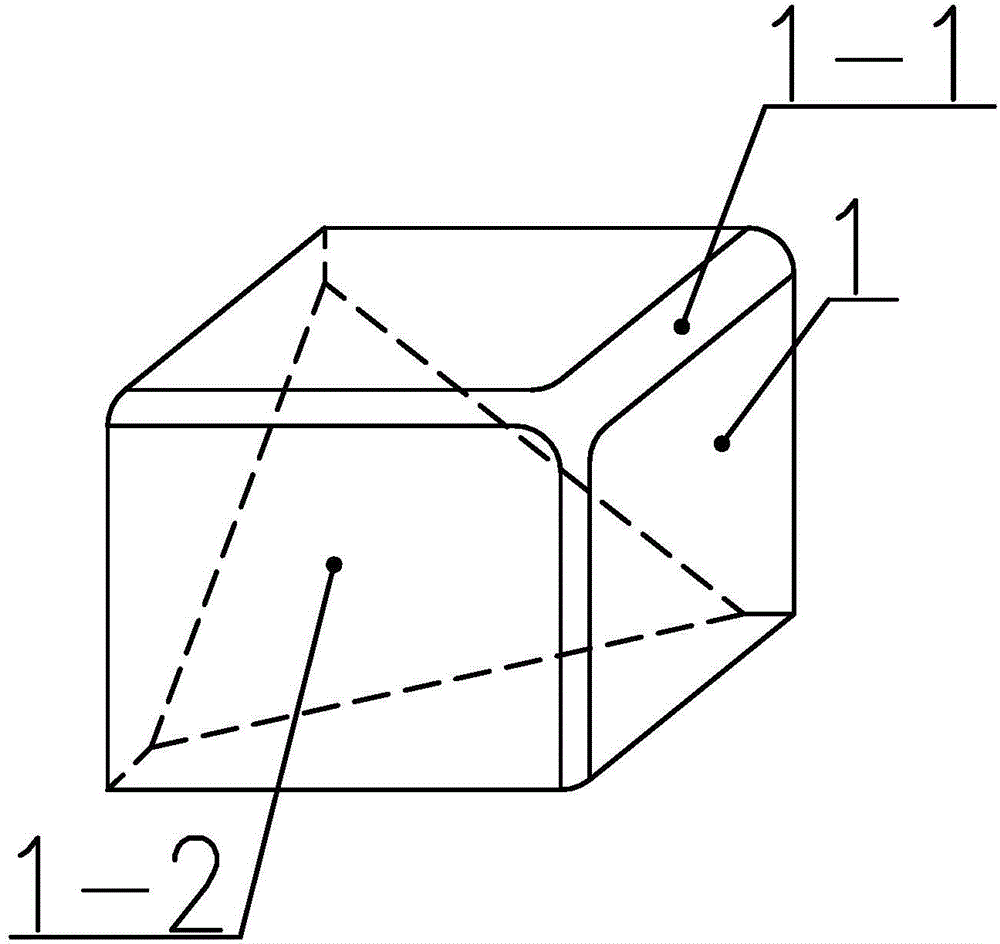
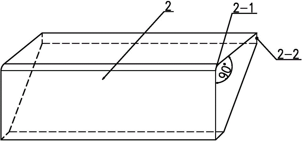
[0041] 1) See figure 2 , image 3 , Is the universal standard preform sand corner preform block 1 and sand prismatic preform block 2, which are finished preforms made in advance. The selected standard prefabricated parts have the same specifications and models as the sand-shaped corner prefabricated block 1 and the sand-shaped prismatic prefabricated block 2.
[0042] 2) See Figure 4 , When processing the moldless sand mold 4, at the installation position of the preform, according to the specifications and dimensions of the sand corner block 1 and the sand prismatic block 2, the sand prismatic bonding surface 3 and the sand corner are bonded. Face 5.
[0043] 3) After the moldless sand mold 4 is finis...
Embodiment 2
[0045] Example 2, when the casting has special quality requirements for a certain plane, it can be made in advance such as Figure 5 or Figure 8 The prefabricated block of sand surface body shown. Then process the moldless sand mold. When processing the sand mold, reserve the installation position of the sand mold surface body prefabricated block. Finally, the prefabricated block of sand surface body is glued to the sand mold, such as Image 6 , Picture 10 Shown.
Embodiment 3
[0046] Example 3, see Picture 10 When the casting has a circular ring structure, the sand mold is first processed according to the shape of the casting, and the paste position of the prefabricated block is reserved, and then the arc-shaped edge prefabricated block 9 is spliced and pasted on the corresponding position of the sand mold. If the arc surface of the casting has special quality requirements, splice and paste the annular structure sand surface body precast block 7 on the corresponding position of the sand mold.
[0047] When splicing all standard preforms, the joints are required to be tight and no molten iron can penetrate during casting.
PUM
| Property | Measurement | Unit |
|---|---|---|
| thickness | aaaaa | aaaaa |
Abstract
Description
Claims
Application Information
 - R&D Engineer
- R&D Manager
- IP Professional
- Industry Leading Data Capabilities
- Powerful AI technology
- Patent DNA Extraction
Browse by: Latest US Patents, China's latest patents, Technical Efficacy Thesaurus, Application Domain, Technology Topic, Popular Technical Reports.
© 2024 PatSnap. All rights reserved.Legal|Privacy policy|Modern Slavery Act Transparency Statement|Sitemap|About US| Contact US: help@patsnap.com