
Split type direct-current charging piles for electric automobiles, system and method

A technology for DC charging piles and electric vehicles, which is applied in the fields of electric vehicle charging technology, electric vehicles, secondary battery charging/discharging, etc., and can solve the problems of low utilization rate of charging piles at night, large cabinet footprint, and large average power, etc. problem, to achieve the effect of flexible charging combination, small footprint and low power

Active Publication Date: 2015-07-29
SHANDONG LUNENG SOFTWARE TECH
View PDF5 Cites 82 Cited by
  • Summary
  • Abstract
  • Description
  • Claims
  • Application Information

AI Technical Summary

Problems solved by technology

[0005] Chinese patent CN 103904737 A proposes a charging scheme with one pile and two chargers. This scheme can only realize the output of a single gun. When one gun is working, the other gun cannot work;
However, this solution requires a large number of DC contactors to realize power expansion, which is costly and occupies a large area of ​​the cabinet; after expansion, only two guns can be output, and the average power of a single gun is relatively large, which also causes charging piles to be damaged. The problem of low nighttime utilization
It can be seen that this kind of charging pile has certain limitations in the construction of charging stations.

Method used


Image

  • Split type direct-current charging piles for electric automobiles, system and method
  • Split type direct-current charging piles for electric automobiles, system and method
  • Split type direct-current charging piles for electric automobiles, system and method

Examples


Embodiment Construction

[0052] The present invention will be further described below in conjunction with the accompanying drawings and embodiments.

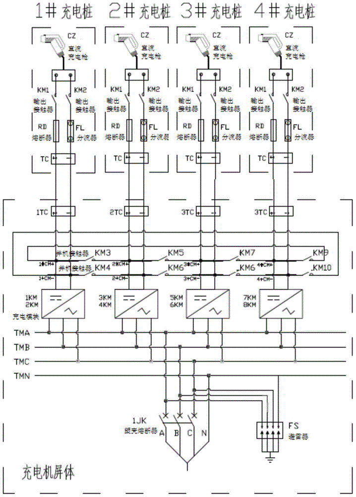
[0053] Such as figure 1 As shown, taking 4 charging piles with a single pile power of 30KW as an example to form a group (but not limited to 4, multiple piles can be paralleled according to actual needs), the core technology of charging piles to realize group parallel work is explained.

[0054] A split DC charging pile, system and method for an electric vehicle, including a charger screen and a DC charging pile;

[0055] The screen body of the charger includes the main switch of AC incoming line, surge arrester, AC bar, grouped charging module, 1# positive and negative bus bar, 2# positive and negative bus bar, 3# positive and negative bus bar, 4# positive and negative bus bar, and parallel Machine contactor, TC terminal, discharge relay, discharge resistor, charging module communication switching intermediate relay, temperature controller, filter fan...


PUM


Abstract

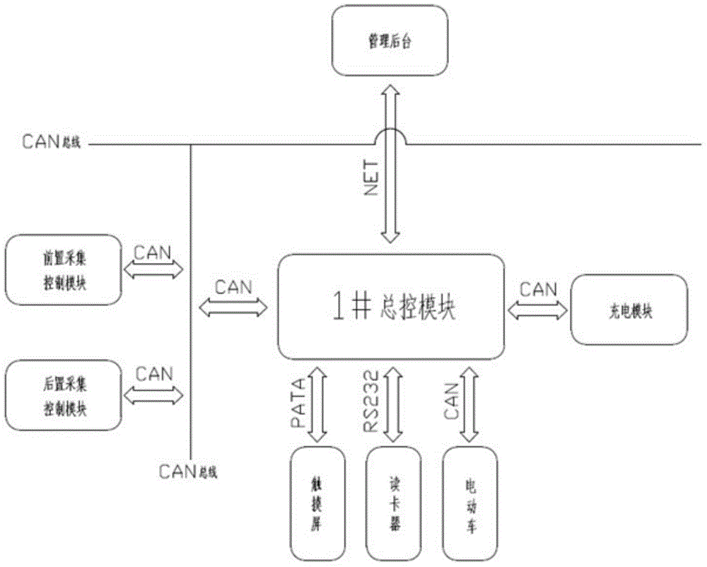
The invention discloses split type direct-current charging piles for electric automobiles, a system and a method. The split type direct-current charging piles for the electric automobiles are in parallel connection to an alternating-current terminal; bus-bars are sequentially connected to one another by charging modules in charger screens of the split type direct-current charging piles through parallel contactors so as to form a loop; a master control module, a front acquiring module and a rear acquiring module of each split direct-current charging pile are connected to one another through a CAN (controller area network) bus; electric energy intelligent load distribution is implemented through the rear acquiring modules by control on switching-off of the parallel contactors; and each charging module is communicated with the master control module of the corresponding direct-current charging pile through a CAN bus, is in parallel connection with a normally open contact of a corresponding intermediate relay and is connected with the adjacent charging modules so that a CAN communication loop is formed. Each charging module is connected with the master control module of the corresponding direct-current charging pile which requires power allocation through the corresponding intermediate relay when responding power allocation; and centralized control is implemented. Moreover, a charging combination mode is flexible, the synthetic cost is low, and the utilization ratio of the charging modules is high.

Description

technical field [0001] The invention relates to a split-type DC charging pile, system and method for electric vehicles. Background technique [0002] The crisis of traditional energy sources such as oil and coal continues to deepen, and the atmospheric environment continues to deteriorate. Energy conservation and emission reduction have become the main direction of future automotive technology development. Continuous breakthroughs in lithium-ion battery technologies such as lithium iron phosphate and modified lithium manganese oxide have opened up broad prospects for the popularization of electric vehicles. The subsequent construction of charging facilities is particularly important, and the construction of charging facilities needs a good operating model as a support. [0003] The charging station is equipped with a small energy storage station to store energy during the valley value of the power grid at night, and the operation plan of energy consumption during the peak p...

Claims


Application Information

Patent Timeline
IPC IPC(8): H02J7/00H02J7/02H01M10/44
CPCY02T90/16Y02T10/7072Y02T90/14B60L53/31B60L53/11B60L53/67H02J2310/48Y02T10/70Y02T90/12H02J7/0013H02J7/0042
Inventor 杨勇陈嵩胡勇童晓霖王立军杨军洲
Owner SHANDONG LUNENG SOFTWARE TECH
Learn More