Vertex-aligning buttress balancing plate type cutting supporting block device

A weighing and cutting technology, applied in excavation, underwater structures, buildings, etc., can solve the problems of more excavation operations, construction difficulties, consumption of large amounts of concrete and stone, etc., to improve environmental protection effects and performance, and reduce human labor. Strength, effect of increasing slip resistance

Inactive Publication Date: 2015-07-29
CHINA RAILWAY ENG CONSULTING GRP CO LTD
View PDF9 Cites 4 Cited by
  • Summary
  • Abstract
  • Description
  • Claims
  • Application Information

AI Technical Summary

Problems solved by technology

However, with the popularization of large-scale machinery, all slopes have now been excavated by large-scale machinery, and the slope of the temporary construction slope is much slower than 1:0.2. The rock-soil boundary condition behind has changed from the original surrounding rock to the backfill soil, and the earth pressure has increased significantly
Because the gravity retaining wall needs to rely on its own gravity to resist the earth pressure, it needs a lot of concrete and stone, and it occupies a large area, requires more excavation operations, and has poor environmental protection; in addition, the plain concrete gravity retaining wall has poor seismic performance. It relies on concrete to resist tension, so the material performance cannot be fully utilized, and the economy is poor; while the mortar-built stone retaining wall has even poorer earthquake resistance, and the labor intensity of workers during construction is extremely high, so it is difficult to effectively guarantee the construction quality
The above problems all indicate that the traditional plain concrete or grouted gravel gravity structure has lagged far behind the actual material, design and construction technical conditions, so it is necessary to update the technology

Method used


Image

  • Vertex-aligning buttress balancing plate type cutting supporting block device
  • Vertex-aligning buttress balancing plate type cutting supporting block device
  • Vertex-aligning buttress balancing plate type cutting supporting block device

Examples


Embodiment Construction

[0022] In order to make the object, technical solution and advantages of the present invention clearer, the present invention will be further described in detail below with reference to the accompanying drawings and examples.

[0023] This embodiment provides a buttress counterweight plate type cutting supporting device.

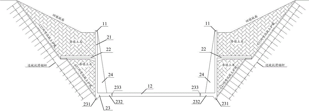
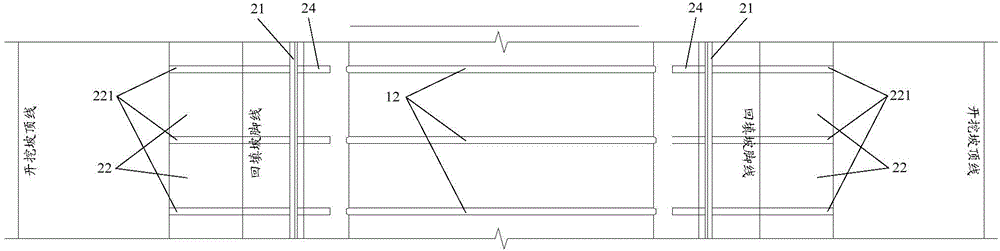
[0024] figure 1 It is a cross-sectional schematic diagram of the buttress counterweight plate type road cutting support device in the embodiment of the present invention. figure 2 It is a top view of the buttress counterweight plate type road cutting support device in the embodiment of the present invention. Such as figure 1 with figure 2 As shown, the buttress counterweight plate type road cutting supporting device in the embodiment of the present invention mainly includes:

[0025] The supporting retaining walls 11 arranged on both sides of the road and extending along the road direction and the inter-wall top beams 12 arranged between two opposite s...


PUM


Abstract

The invention discloses a vertex-aligning buttress balancing plate type cutting supporting block device, which comprises supporting block walls and an inter-wall top beam, wherein the supporting block walls are respectively arranged on the two sides of a road and extend along the direction of the road; the inter-wall top beam is arranged between the two opposite supporting block walls; each of the supporting block walls comprises a block wall panel and a beam type balancing plate, and the beam type balancing plate is arranged on the outer side of the block wall panel and is vertical to the block wall panel; a slope type wall heel is arranged at the bottom of each block wall panel; each slope type wall heel comprises a wall heel and a wall toe plate, the wall heel is arranged at the bottom of the block wall panel, and the wall toe plate is arranged on the inner side of the bottom of the block wall panel and is vertical to the block wall panel; the two ends of the inter-wall top beam are respectively resisted against the wall toe plates of the supporting block walls on the two sides of the road. The vertex-aligning buttress balancing plate type cutting supporting block device provided by the invention can be used for reducing the on-site labor intensity, improving the operation condition, increasing the environmental protection effect and reducing the engineering cost.

Description

technical field [0001] The invention relates to the technical field of cutting engineering, in particular to a buttress counterweight plate type cutting support device. Background technique [0002] At present, the existing road and railway slope retaining structures often adopt a gravity-type inclined structure. The breast slope in this structure is generally 1:0.1 to 1:0.2, and the construction conditions for it are manual excavation. However, with the popularization of large-scale machinery, all slopes have now been excavated by large-scale machinery, and the slope of the temporary construction slope is much slower than 1:0.2. The rock-soil boundary conditions behind it changed from original surrounding rock to backfill soil, and the earth pressure increased significantly. Because the gravity retaining wall needs to rely on its own gravity to resist the earth pressure, it needs a lot of concrete and stone, and it occupies a large area, requires more excavation operations...

Claims


Application Information

Patent Timeline
Patent Type & Authority Applications(China)
IPC IPC(8): E02D17/20
CPCE02D17/20E02D29/02
Inventor 吕刚赵勇倪光斌林传年唐国荣田四明李汶京石山陈学峰刘建友于晨昀岳岭张矿三褚冠男
Owner CHINA RAILWAY ENG CONSULTING GRP CO LTD
Why Eureka
Try Eureka