
A hingeless rocker slider mechanism and a weft-connecting rapier for rapier looms

A rocker slider, rapier loom technology, applied in looms, textiles, textiles and papermaking, etc., can solve problems such as hinge shaft flying out, excessive warp tension change, and breaking cloth, etc., to improve clamping force, improve adaptability, and stabilize the yarn clamping effect

Active Publication Date: 2016-04-06
徐向忠
View PDF8 Cites 0 Cited by
  • Summary
  • Abstract
  • Description
  • Claims
  • Application Information

AI Technical Summary

Problems solved by technology

However, the number of yarn unwinding and clamping actions of this kind of sword head reaches 180-450 times or min. During such high-frequency operation, the hinges and screws between the angle-shaped connecting rod and the outer sleeve and between the inner sleeve and the connecting plate are fixed. There will be damage, such as the hinge shaft flying out, causing the sword head to be damaged and unable to work and break the cloth; at the same time, the sword head of this structure cannot be miniaturized, so that the shed of the loom cannot be reduced, which makes the speed of the loom It cannot be lifted; and the large shed makes the warp yarn tension change too much, which is easy to cause damage to the warp yarn

Method used


Image

  • A hingeless rocker slider mechanism and a weft-connecting rapier for rapier looms
  • A hingeless rocker slider mechanism and a weft-connecting rapier for rapier looms
  • A hingeless rocker slider mechanism and a weft-connecting rapier for rapier looms

Examples


Embodiment 1

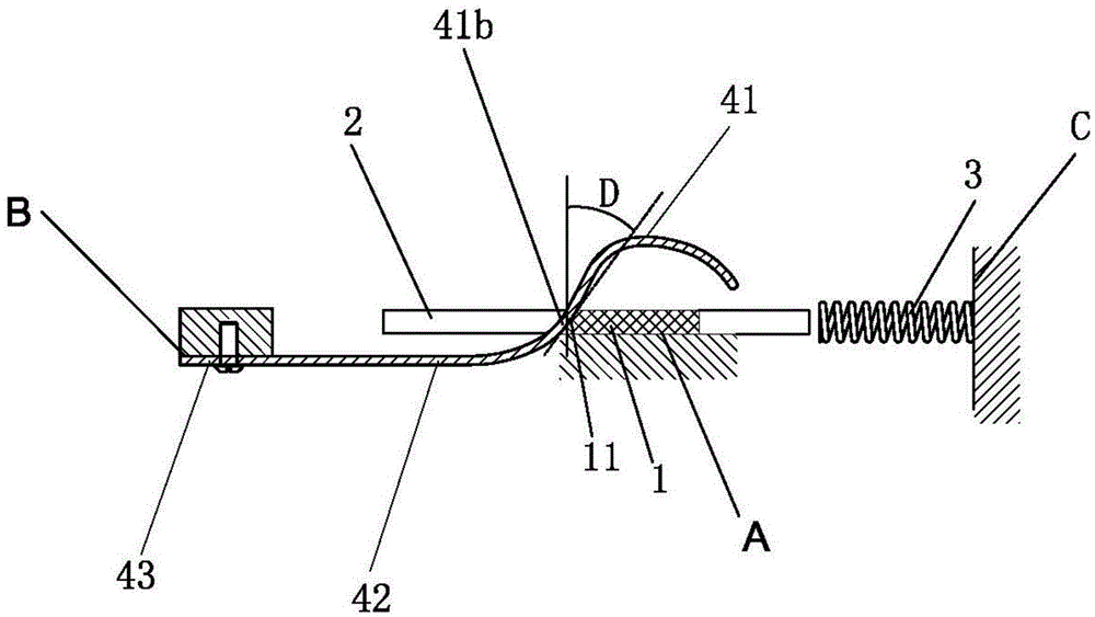
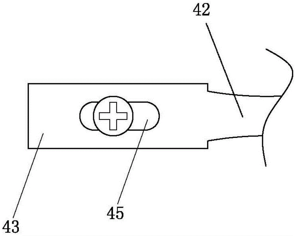
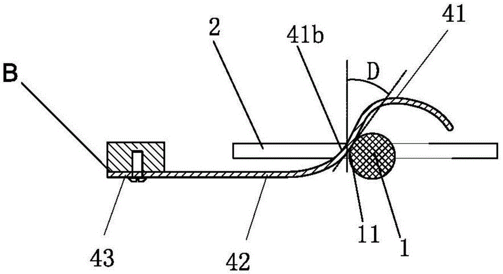
[0036] Reference attached Figure 1-2 , A hingeless rocker slider mechanism, including a rocker, a slider 1 roughly in the shape of a rectangular parallelepiped, the slider 1 is slidably arranged on the plane A, and the slider 1 is provided with a connecting part 2 fixed with the load. One end of the positioning spring 3 abuts against the connecting part 2 and the other end of the return spring 3 abuts against a plane C perpendicular to the plane A. The return spring 3 drives the slider 1 to return to drive the load back. The rocker is an elastic component. The rocker includes a driving part, an elastic deformation part 42 and a positioning part 43. The positioning part 43 is provided with a long waist hole 45. The bolt overlong waist hole 45 is fixed to plane B. Plane B is located on the left of plane A. Side; planes A, B, and C are all planes of the machine body, such as the sword head shell of the weft sword head, the shell of the travel switch, etc.; the driving part include...

Embodiment 2

[0040] See Figure 4 The difference between Embodiment 2 and Embodiment 1 is that the other end of the elastically deformable part is connected to one end of the input part 41, the other end of the input part 41 is connected to the output part 41b, and the shape of the output part 41b and the input part 41 is a circle. shape.

Embodiment 3

[0042] See Figure 5 The difference between embodiment 3 and embodiment 1 is that one end of the positioning portion 43 is connected to one end of the elastic deformation portion 42, the other end of the elastic deformation portion 42 is connected to one end of the input portion 41, and the other end of the input portion 41 is connected to the output portion. 41b is connected, and the shape formed by the input part 41 and the output part 41b is an arched bridge shape, and the part of the output part 41b abuts against the inclined surface of the upper left corner of the slider.

[0043] Such as Image 6 As shown in the structure, the hingeless rocker slider mechanism of the present invention can also be transformed into this structure. The structure includes a rocker and a slider 1 with a rectangular cross-sectional shape. The slider 1 is slidably arranged on the plane A. 1 is provided with a connecting portion 2 fixed with a load, one end of the return spring 3 abuts against the c...


PUM


Abstract

The invention discloses a hingeless rocking bar slide block mechanism, which comprises a rocking bar, a slide bock and a return spring, wherein the slide block is glidingly arranged on a plane A, the return spring drives the slide block to return, and the slide block is used for driving a load. The hingeless rocking bar slide block mechanism is characterized in that the rocking bar is an elastic component, and comprises a driving part, an elastic deformation part and a positioning part, the positioning part is fixed with a plane B, and the positioning part is connected with the driving part through the elastic deformation part; the driving part comprises an input part and an output part, the output part is abutted against one surface of the slide block, the two butted surfaces are anastomotic with each other, and when the input part is stressed and is downwards pressed, the elastic deformation part is stressed to deform, so that the output part generates displacement, and the slide block is pushed to move; the plane A and the plane B are respectively planes on a machine body; the rigidity of the driving part is greater than that of the elastic deformation part. The hingeless rocking bar slide block mechanism has the advantages that after the structure is adopted, a transmission structure is simplified, so that a rapier head manufactured by the slide block mechanism is smaller and lighter.

Description

Technical field [0001] The invention relates to a hingeless rocker slider mechanism and a weft-joining rapier for rapier looms. Background technique [0002] In the light industrial machinery fields such as textile machinery, packaging machinery and switch appliances, in order to change the direction of force, the movement direction and movement mode are often used by crank slider mechanism, swing guide rod mechanism, etc., these mechanisms are composed of rods and hinges Therefore, there are disadvantages such as many parts, large structure, occupying a large space, and high cost. [0003] For example, the publication number is CN2011655578, and the utility model patent named "weft splicing head of loom" discloses a weft splicing head of a loom, which includes a housing and a release mechanism. The release mechanism includes a housing installed in the housing. The outer sleeve, the angular connecting rod fixedly connected with one end of the outer sleeve, the inner sleeve install...

Claims


Application Information

Patent Timeline
Patent Type & Authority Patents(China)
IPC IPC(8): D03D47/27D03D47/23
Inventor 徐向忠
Owner 徐向忠
Learn More