
Ball Link Robotic Arm

A mechanical arm, link-type technology, applied in the direction of manipulator, program-controlled manipulator, claw arm, etc., can solve the problem of limiting the rotation angle of the bending rod

Active Publication Date: 2016-11-23
HIWIN TECH
View PDF6 Cites 0 Cited by
  • Summary
  • Abstract
  • Description
  • Claims
  • Application Information

AI Technical Summary

Problems solved by technology

[0004] In addition, in the aforementioned mechanical arm, since the movements of the bending rods are mutually restrained, and the driving device that drives the rotation of the bending rods will also cause restrictions in space, thereby limiting the rotation angle of each bending rod, therefore The robotic arm can only move microsurgical instruments within a fairly limited working range

Method used


Image

  • Ball Link Robotic Arm
  • Ball Link Robotic Arm
  • Ball Link Robotic Arm

Examples


Embodiment Construction

[0013] The applicant first explains here that in the embodiments and drawings to be described below, the same reference numerals denote the same or similar elements or structural features. Secondly, when it is mentioned that an element is arranged on another element, it means that the aforementioned element is directly arranged on the other element, or that the aforementioned element is indirectly arranged on the other element, that is, there is a gap between the two elements. Set with one or more other elements.

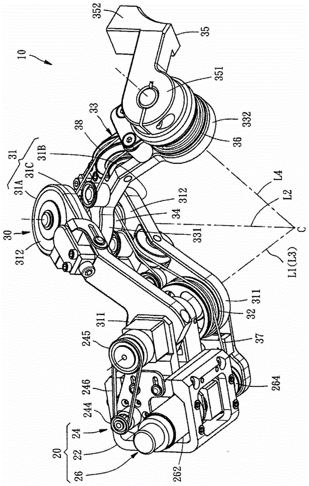
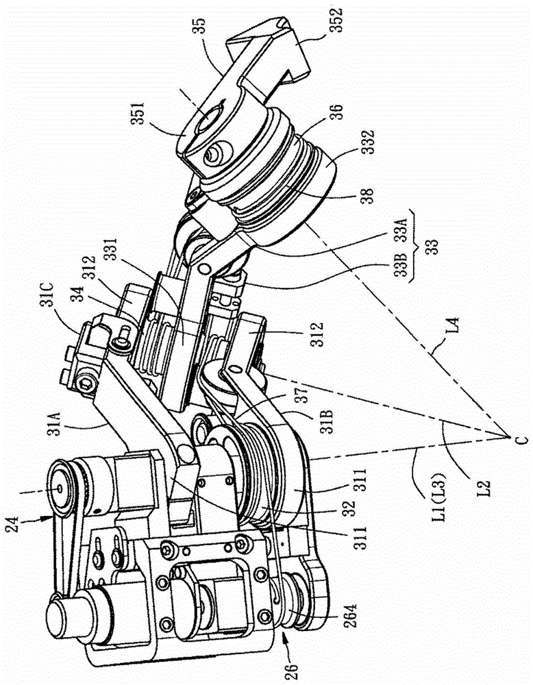
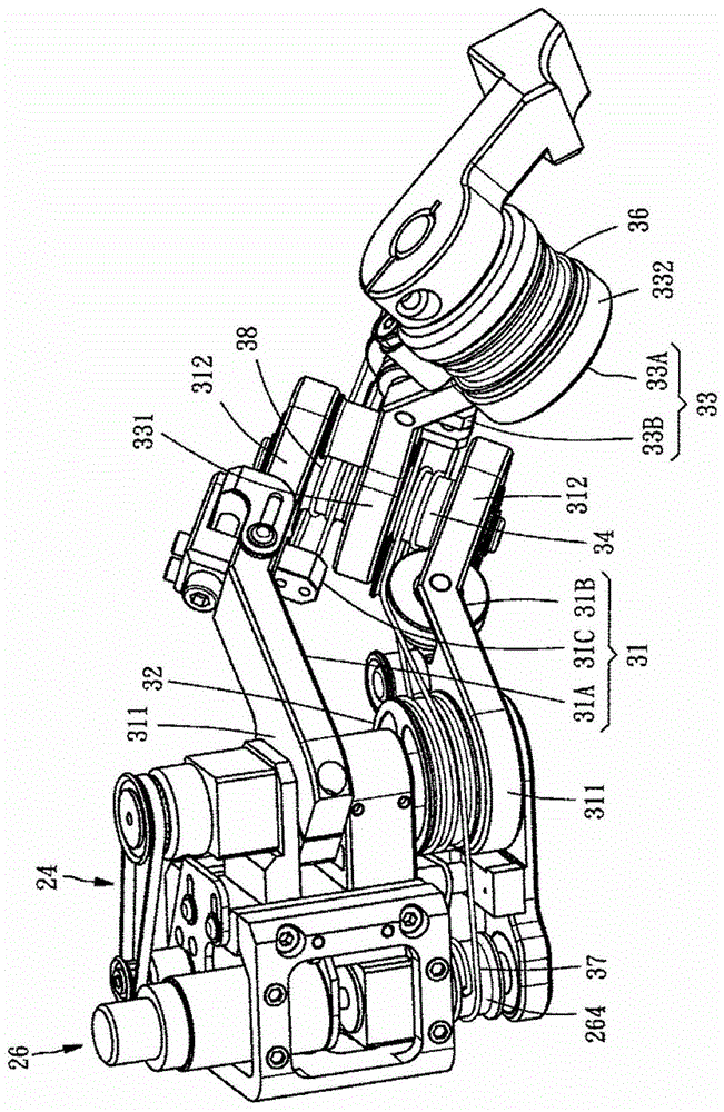
[0014] Please see first Figure 1 to Figure 4 , The ball-link robot arm 10 provided by a preferred embodiment of the present invention includes a driving device 20 and a ball mechanism 30 .

[0015] What needs to be explained here is that the "spherical" in the "spherical link type mechanical arm" and "spherical mechanism" described in the present invention refers to the rotation axis of each rotatable part (that is, the rotation axis described below) The first, s...


PUM


Abstract

The utility model discloses a spherical connecting rod type mechanical arm. The spherical connecting rod type mechanical arm comprises first and second bent rods, an appliance rod, first, second and third proportion wheels and first and second flexible ropes, which are pivoted with one another in sequence, wherein first to fourth hypothetical axes crossed at a spherical rotating centre can be defined; the first bent rod and the first proportion wheel are respectively driven to rotate through utilizing the first and third hypothetical axes as centers; the first flexible rope winds around the first and second proportion wheels and is used for the second bent rod; moreover, when the first proportion wheel is rotating, the first flexible rope drives the second proportion wheel and the second bent rod to rotate by utilizing the second hypothetical axis as the center; the second flexible rope winds around the second and third proportion wheels and is fixed at the first bent rod; when the second proportion wheel is rotating, the second flexible rope drives the third proportion wheel and the appliance rod to rotate through utilizing the fourth hypothetical axis as the center. The mechanical arm has small volume; operators can act the mechanical arm without any hindrance and the working area is relatively big.

Description

technical field [0001] The present invention relates to a mechanical arm, in particular to a spherical link type mechanical arm. Background technique [0002] Please refer to the invention patent case of China Taiwan Patent Application No. 102121198. This patent provides a mechanical arm using a spherical five-bar linkage mechanism. Both pass through the same spherical center of rotation. The mechanical arm is mainly used in a minimally invasive surgery system to install a micro-surgical instrument and precisely control the swing direction and swing angle of the micro-surgical instrument. [0003] However, the aforementioned robotic arm has a considerable volume because it includes at least four curved rods, and the minimally invasive surgery system usually includes many robotic arms to install many microsurgical instruments with different functions. In other words, if the volume of the robotic arm can be reduced, it will be beneficial to the space configuration of the min...

Claims


Application Information

Patent Timeline
Patent Type & Authority Patents(China)
IPC IPC(8): B25J9/02B25J18/00
Inventor 王仁政
Owner HIWIN TECH
Learn More