Drawing method of main busbar connection diagram between dry-type distribution transformer and low-voltage switchgear

A technology for distribution transformers and low-voltage switchgears, which is applied in the field of drawing main bus connection diagrams between dry-type distribution transformers and low-voltage switchgears, and can solve problems such as high probability of errors, long connection diagram cycle, and time-consuming

Active Publication Date: 2017-08-25
HEBEI UNIV OF TECH
View PDF5 Cites 0 Cited by
  • Summary
  • Abstract
  • Description
  • Claims
  • Application Information

AI Technical Summary

Problems solved by technology

According to statistics, each dry-type distribution transformer involves drawing the main busbar connection diagram with the input copper bar of the low-voltage switchgear, and more skilled technicians draw a set of connections between the dry-type distribution transformer and the low-voltage switchgear. main bus connection Figure 1 Generally, it takes 1 day, which not only takes a long period to draw the connection diagram, but also takes a lot of time, and the probability of errors is high

Method used


Image

  • Drawing method of main busbar connection diagram between dry-type distribution transformer and low-voltage switchgear
  • Drawing method of main busbar connection diagram between dry-type distribution transformer and low-voltage switchgear
  • Drawing method of main busbar connection diagram between dry-type distribution transformer and low-voltage switchgear

Examples


Embodiment 1

[0161] In this embodiment, dry-type distribution transformers adopt 1000KVA, 10KV / 0.4KV dry-type cast resin distribution transformers, the low-voltage side voltage is 400V, and the radii of the first rejection zone and the second rejection zone are both 50mm.

[0162] In this embodiment, the drawing method of the main busbar connection diagram between the dry-type distribution transformer and the low-voltage switchgear, the specific steps are as follows:

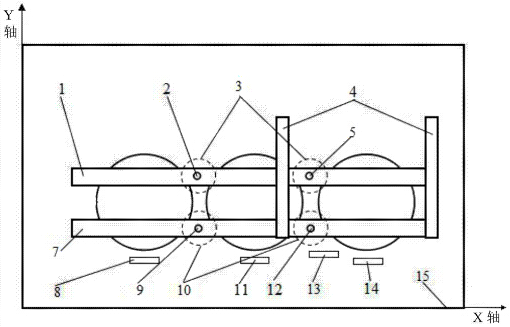
[0163] The first step is to establish the XY coordinate system of the dry-type distribution transformer in the dry-type distribution transformer cabinet 15:

[0164] Place the dry-type distribution transformer in the dry-type distribution transformer cabinet 15. From the top view of the dry-type distribution transformer cabinet, the lower vertex on the side close to the c-phase copper bar 8 on the low-voltage side of the dry-type distribution transformer is defined as The origin of the coordinates, the horizontal direction o...

Embodiment 2

[0189] Except for the following differences from Embodiment 1, the drawing method of the main busbar connection diagram between other dry-type distribution transformers and low-voltage switchgear is the same as Embodiment 1:

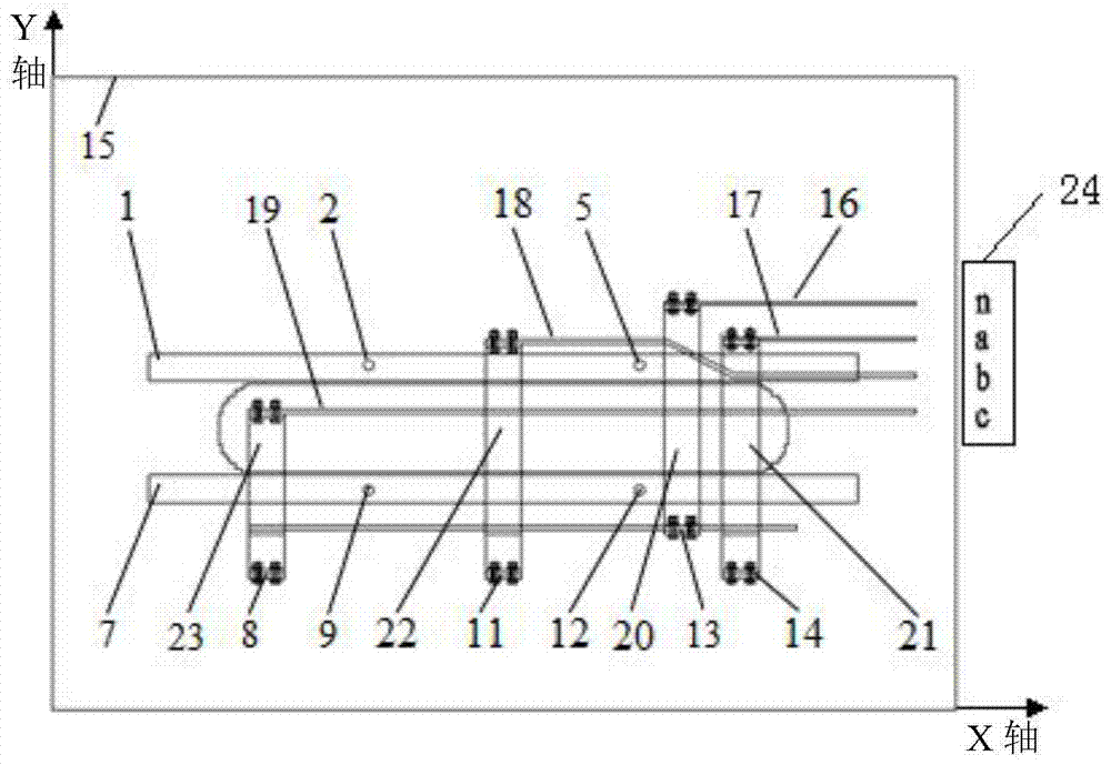
[0190] In this embodiment, the dry-type distribution transformer adopts 1600KVA, 10KV / 0.4KV dry-type resin cast distribution transformer, and the outlet mode of the input copper bar 24 of the low-voltage switchgear is selected as the left outlet, and the input copper bar 24 of the low-voltage switchgear is in the negative direction of the Y axis. The phase sequence on is abcn;

[0191] From the top view coordinate diagram of dry-type distribution transformer (see image 3 ), the coordinate origin is set at the lower left corner of the dry-type distribution transformer cabinet 15, the X positive semi-axis is horizontally to the right, and the Y positive semi-axis is vertically upward (that is, the dry-type distribution transformer is directed from the low...

Embodiment 3

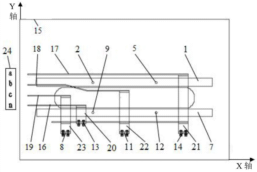
[0206] Except for the following differences from Embodiment 1, the drawing method of the main busbar connection diagram between other dry-type distribution transformers and low-voltage switchgear is the same as Embodiment 1:

[0207] The phase sequence of the input copper bar 24 of the low-voltage switchgear in the negative direction of the Y axis is cban.

[0208] Draw the copper bars of each connected line:

[0209] B-1. Determine the position and shape of the copper bar connected to line c:

[0210] The Y-axis coordinate of the c-phase copper bar of the input copper bar 24 of the low-voltage switchgear is not within the Y-axis coordinate range of the two rejection areas, and the copper bar of the c-connected line is a straight copper bar; the coordinates of the starting point of the copper bar of the c-connected line are the low-voltage switchgear Input the coordinates ptc(x 24c ,y 24c ), the X-axis coordinate of the end point of the copper bar of the c-connected line is...


PUM


Abstract

The method for drawing the main busbar connection diagram between the dry-type distribution transformer and the low-voltage switchgear of the present invention relates to the conductive connection of the transformer. The drawing method determines the coordinate values ​​of the relevant parameters in the established XY coordinate system; the drawing method is written in the Visual C++ language. In the human-computer interaction interface, the data required for drawing is input into the computer. Determine the position and shape of each connected copper bar according to the input outlet method, the phase sequence of the input copper bar of the low-voltage switchgear and the coordinate value of each phase of the input copper bar of the low-voltage switchgear, and draw each connected copper bar. According to the coordinate values ​​of the low-voltage side copper bars of each phase of the dry-type distribution transformer, determine the position and shape of each phase outgoing copper bar of the dry-type distribution transformer, and draw the outgoing copper bars of each phase of the dry-type distribution transformer. The drawing method of the invention can significantly shorten the design cycle of the main busbar connection diagram between the dry-type distribution transformer and the low-voltage switchgear, improve the quality of the drawings, and meet the design requirements.

Description

technical field [0001] The technical solution of the present invention relates to the conductive connection of transformers, in particular to a method for drawing a main busbar connection diagram between a dry-type distribution transformer and a low-voltage switchgear. Background technique [0002] The dry-type distribution transformer is placed in the cabinet during application, and its high-voltage side is connected to the high-voltage switch through cables, and its low-voltage side copper bar is connected to the input copper bar of the low-voltage switch cabinet. Since the relative positions of the dry-type distribution transformer and the low-voltage switchgear vary greatly, the positions of the copper bars on the low-voltage side of the dry-type distribution transformer and the input copper bars of the low-voltage switchgear have many situations. Almost every dry-type distribution transformer A set of main bus connection diagrams must be redrawn. At present, the main b...

Claims


Application Information

Patent Timeline
Patent Type & Authority Patents(China)
IPC IPC(8): G06F17/50G06Q50/06
Inventor 杜江李爱铂张烨烨王君
Owner HEBEI UNIV OF TECH
Why Eureka
Try Eureka