Self-aligning roller bearing

A self-aligning roller bearing and roller technology, applied in the field of bearings, can solve the problems of bearing wear, lubricating oil difficult to enter the bearing, bearing deformation, etc., and achieve the effect of simple assembly

Active Publication Date: 2015-07-22
SCHAEFFLER TECH AG & CO KG
View PDF12 Cites 5 Cited by
  • Summary
  • Abstract
  • Description
  • Claims
  • Application Information

AI Technical Summary

Problems solved by technology

[0009] Another problem to be solved by the present invention is: when assembling the existing spherical roller bearings, it is easy to cause bearing deformation; the gyroscopic motion of the rollers will be intensified; for wide series spherical roller bearings, the processing of the outer ring is increased Difficulty; bearing wear is relatively serious; under the obstruction of the guide ring, it is difficult for lubricating oil to enter the inside of the bearing

Method used


Image

  • Self-aligning roller bearing
  • Self-aligning roller bearing
  • Self-aligning roller bearing

Examples


Embodiment Construction

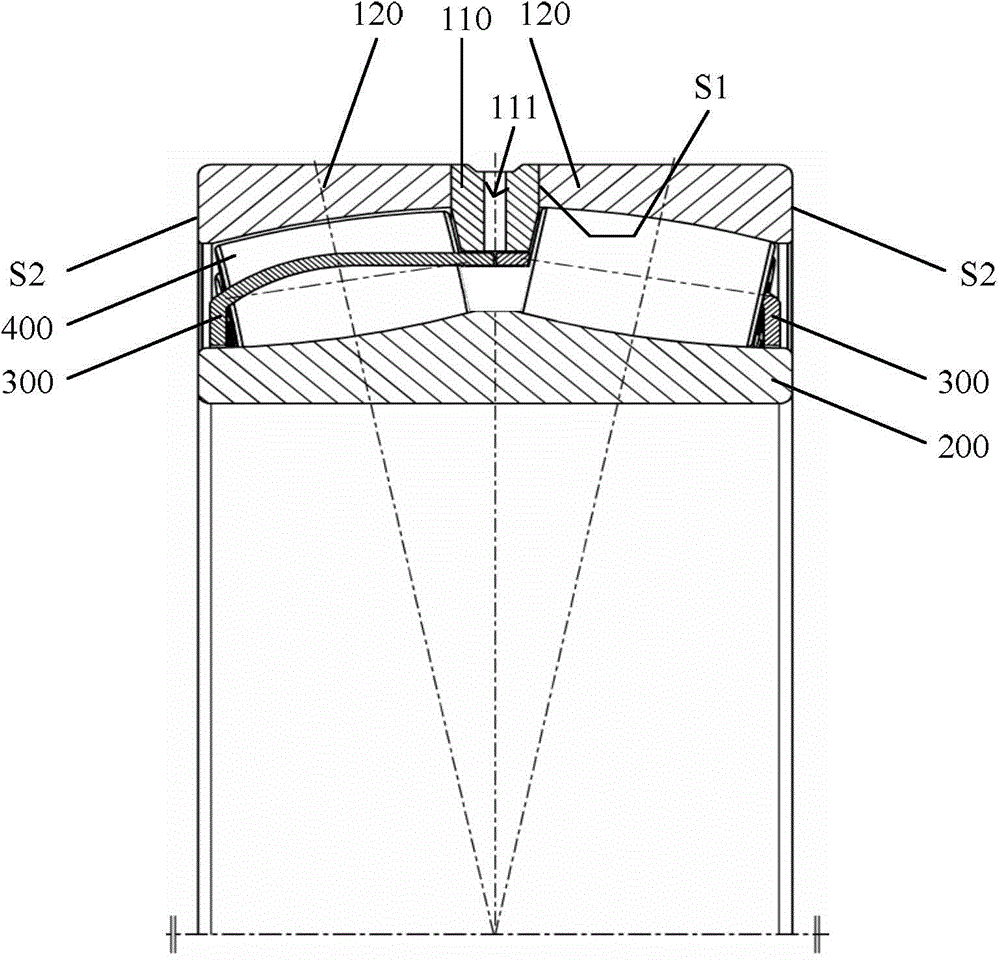
[0033] combine figure 2 and image 3 As shown, the spherical roller bearing of the first embodiment of the present invention includes:

[0034] The outer ring divided into two outer ring units 120 in the axial direction;

[0035] A guide ring 110 is arranged axially between the two outer ring units 120, and the two axial end faces of the guide ring 110 are respectively in contact with the inner end faces S1 of the two outer ring units 120, defining that the outer ring units 120 are not in contact with the guide ring 110 The end face in contact is the outer end face S2;

[0036] The inner ring 200 provided in the two outer ring units 120 and the guide ring 110, the inner ring 200 is a ribless inner ring;

[0037] The cage 300 with pockets located between the inner ring 200 and the two outer ring units 120 and the guide ring 110 is a split window type cage, and the pockets on the window type cage are closed Yes, the guide ring 110 is radially located outside the cage 300, a...


PUM


Abstract

A self-aligning roller bearing comprises an outer ring, an inner ring arranged inside the outer ring, a retainer which is positioned between the outer ring and the inner ring and has a pocket and two columns of rollers which are circumferentially arranged at intervals and positioned inside the pocket. The outer ring is axially divided into two outer-ring units. A guide ring is axially arranged between the two outer-ring units. The guide ring radially extends between the two columns of rollers and is positioned on the outside of the retainer. According to the invention, the problem that existing self-aligning roller bearings are complex to assemble and bearings are easy to deform during assembling of the bearings is solved, the influence of gyratory motion of the rollers is minimized, and the difficulty of processing the outer ring in the wide series self-aligning roller bearing is reduced.

Description

technical field [0001] The present invention relates to the technical field of bearings, in particular to a spherical roller bearing (Spherical Roller Bearing, SRB for short). Background technique [0002] Such as figure 1 As shown, an existing spherical roller bearing includes: an outer ring 1; an inner ring 2 located inside the outer ring 1; two cages 3 located between the outer ring 1 and the inner ring 2, and two rows along the circumferential direction The rollers 4 are arranged at intervals, and the rollers 4 are located in the pockets (not marked) of the cage 3; the middle retaining ring 5 is located between the two rows of rollers 4, and the middle retaining ring 5 is located between the cage 3 and the inner ring 2 between. [0003] The assembly steps of the self-aligning roller bearing are as follows: put the two cages 3 and the intermediate retaining ring 5 on the inner ring 2, and in a row of pockets of the cage 3, there are no pockets in several pockets that ar...

Claims


Application Information

Patent Timeline
IPC IPC(8): F16C23/08F16C33/46
Inventor 刘际轩周国
Owner SCHAEFFLER TECH AG & CO KG
Why Eureka
Try Eureka